Project Paper Weight

bggrnchvy

New member
Mar 23, 2012
93
2
0
Project Paper Weight

This is a stock to current description of how I managed to turn my truck into something even I have difficulty acknowledging the usefulness of.

The Beginning

Stock.jpg

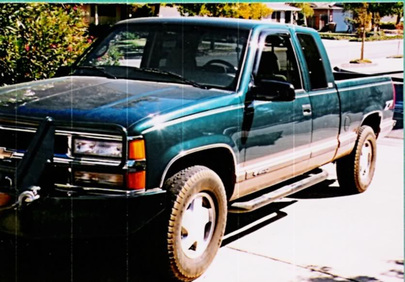
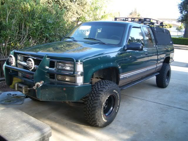
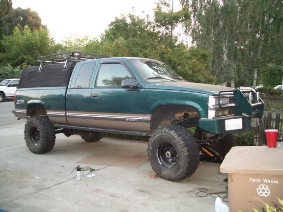
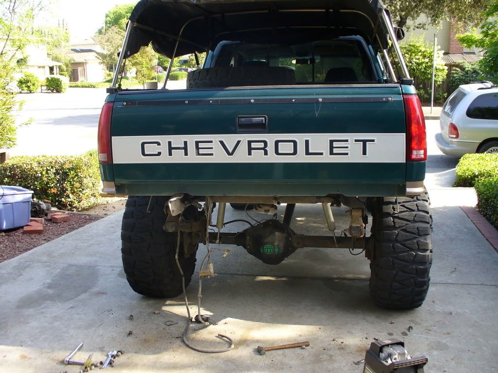
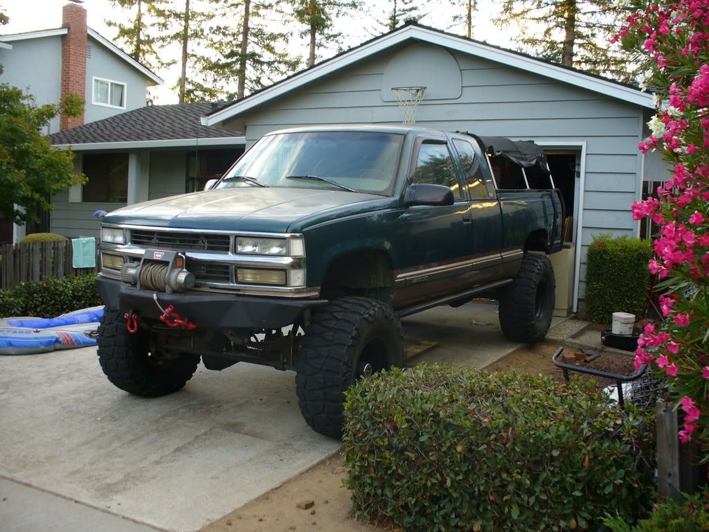
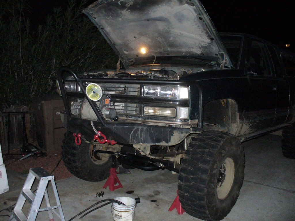
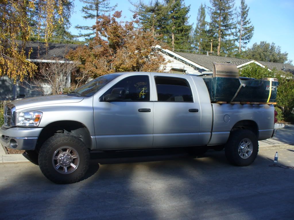
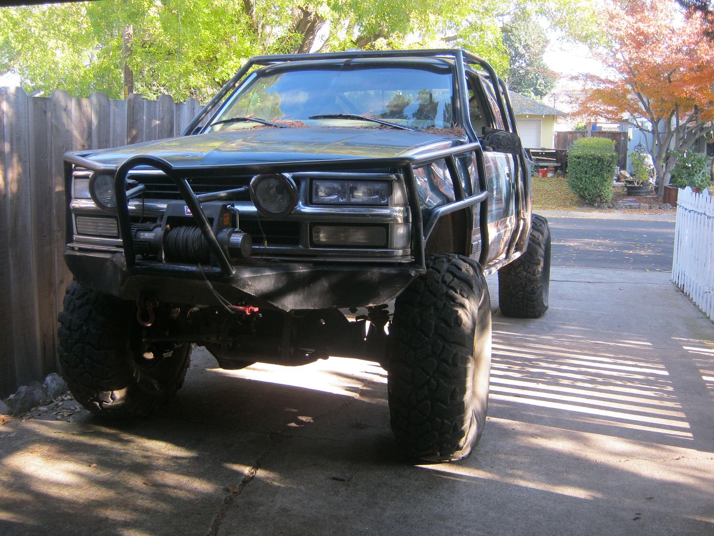
As purchased, June 03. Only picture I have, wish I had been more judicious in capturing some pics.

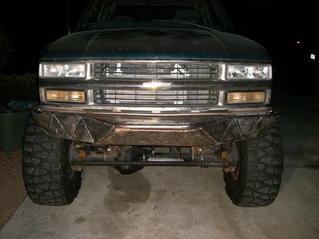
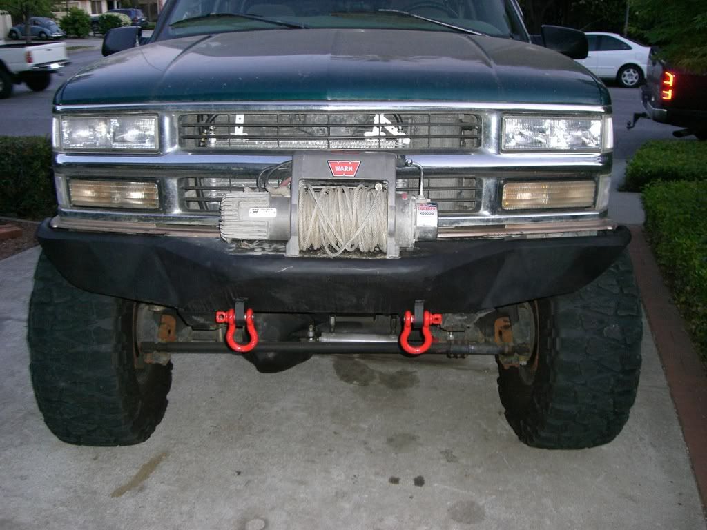
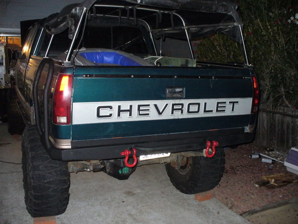
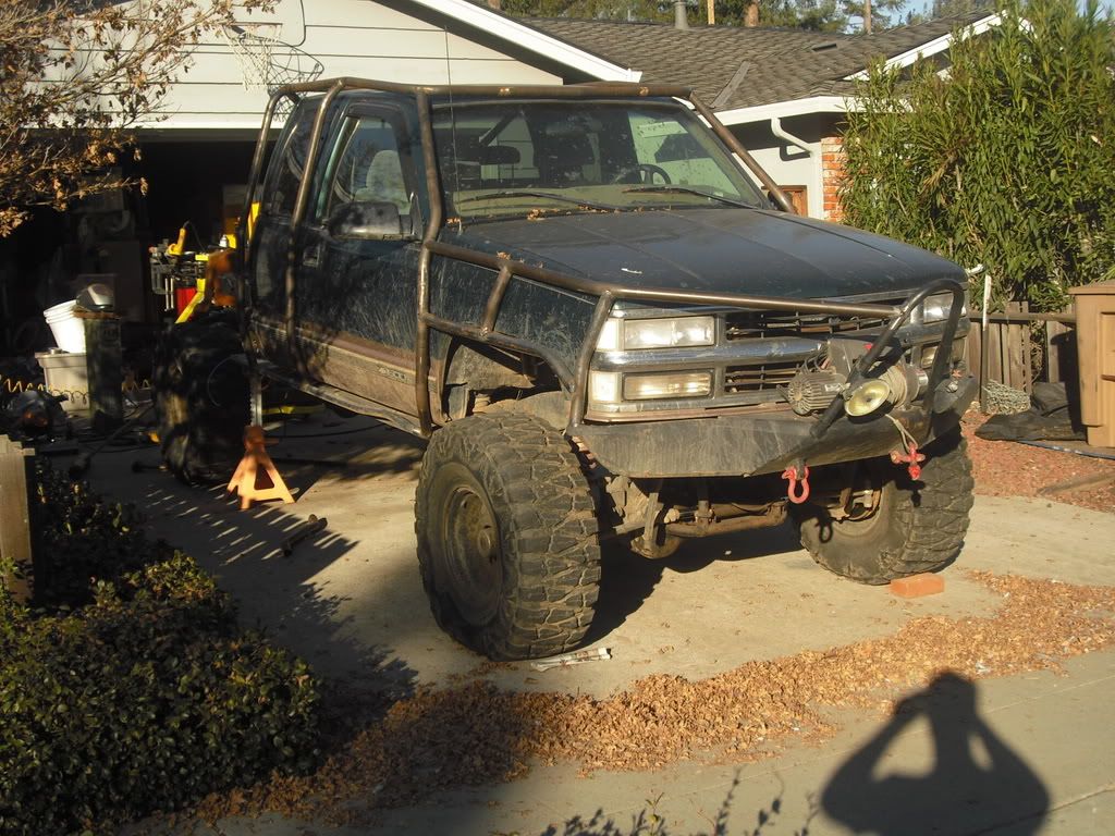
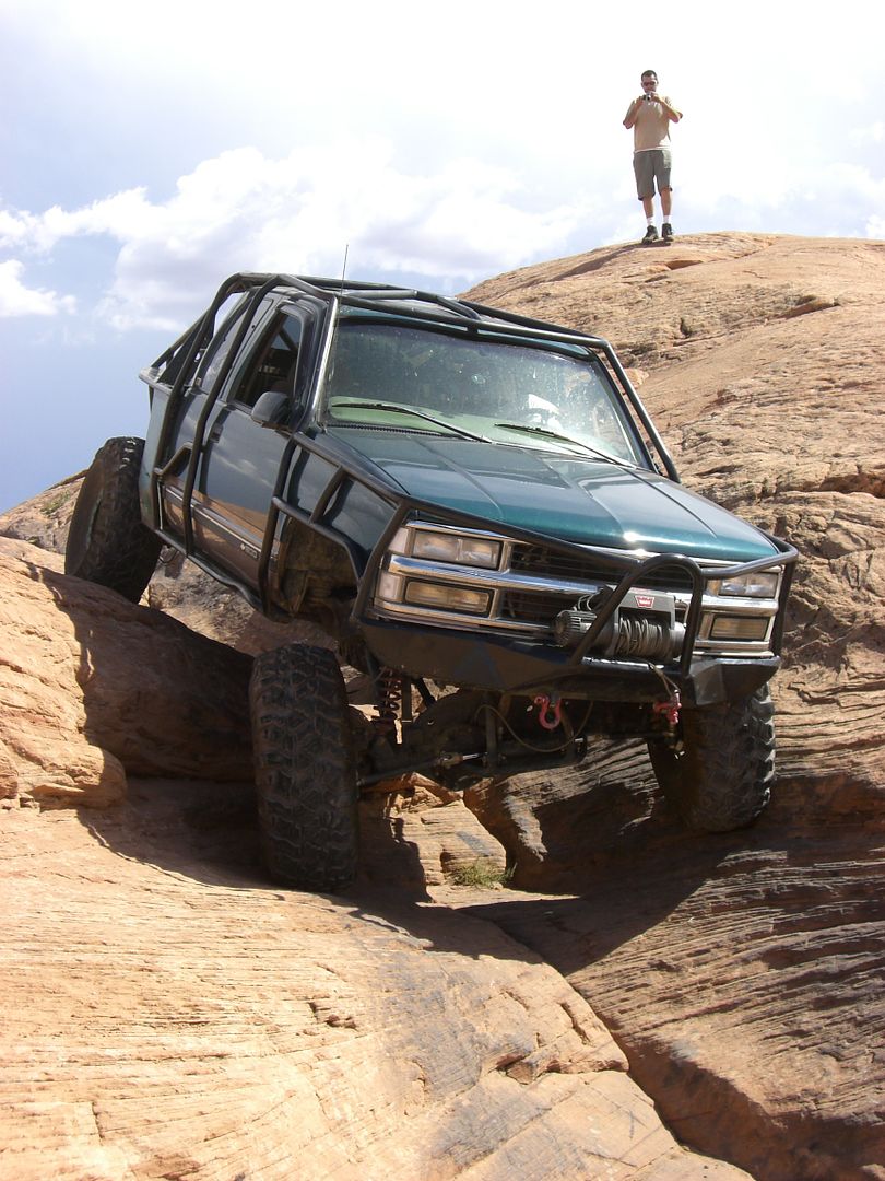
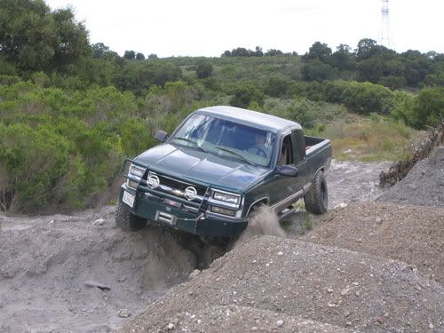
The first round of mods were tame, I knew it was going to be driven a lot and I didn't have the money to regear. It ended up with a 6" Superlift kit and some 15x10 steelies wrapped in 33" BFG A/T's. The bumper and winch were already on the truck.

Chevypicbenttubeflexed.jpg


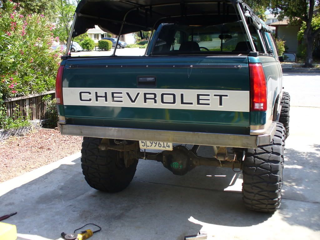
I threw on some nerf bars which were bent and crushed in short order.

469624_12_full.jpg


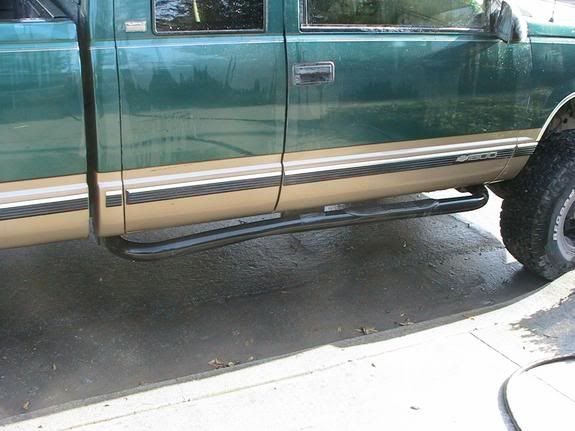
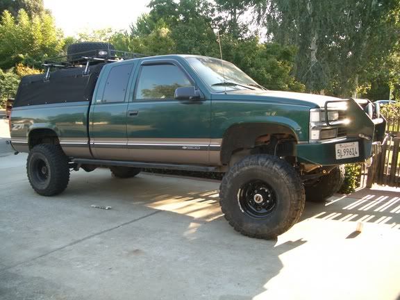
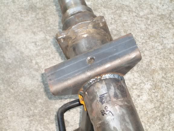
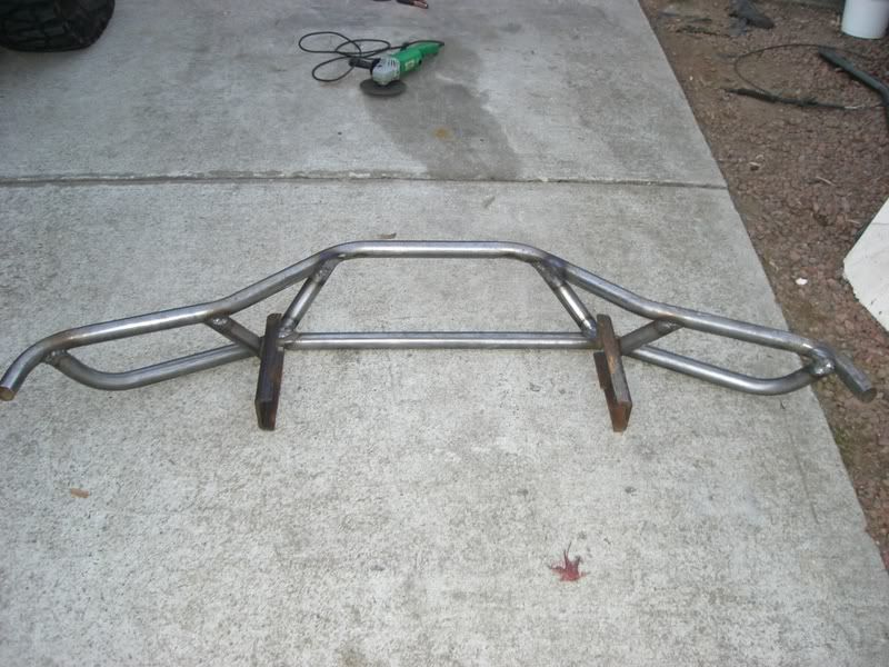
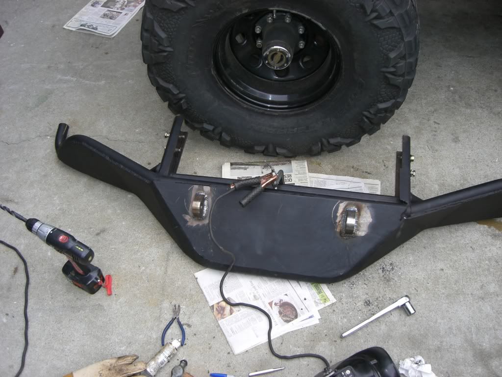
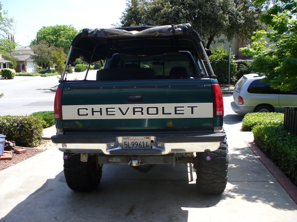
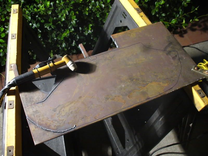
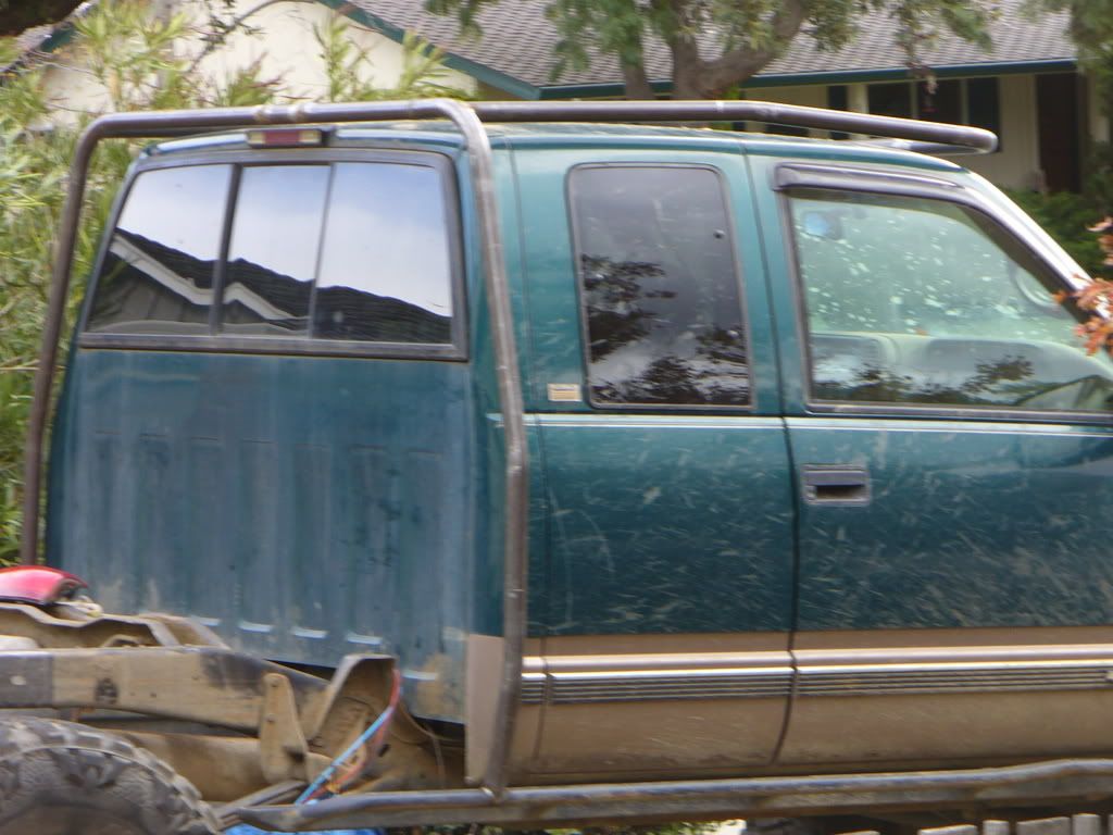
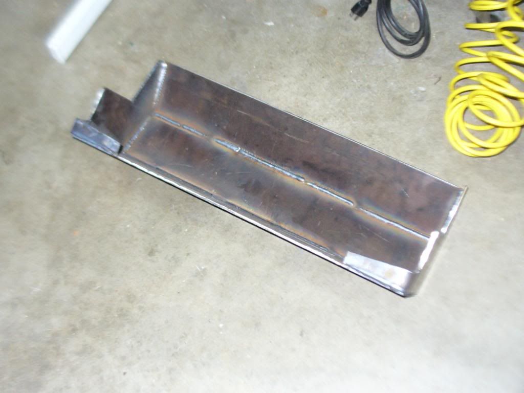
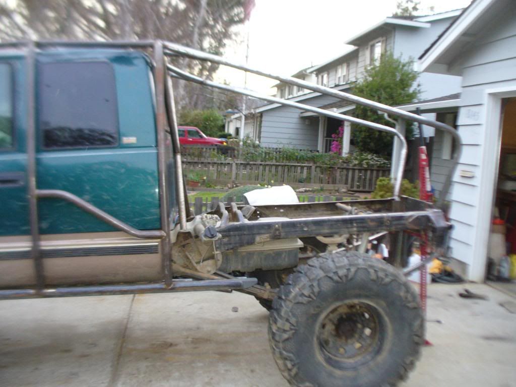
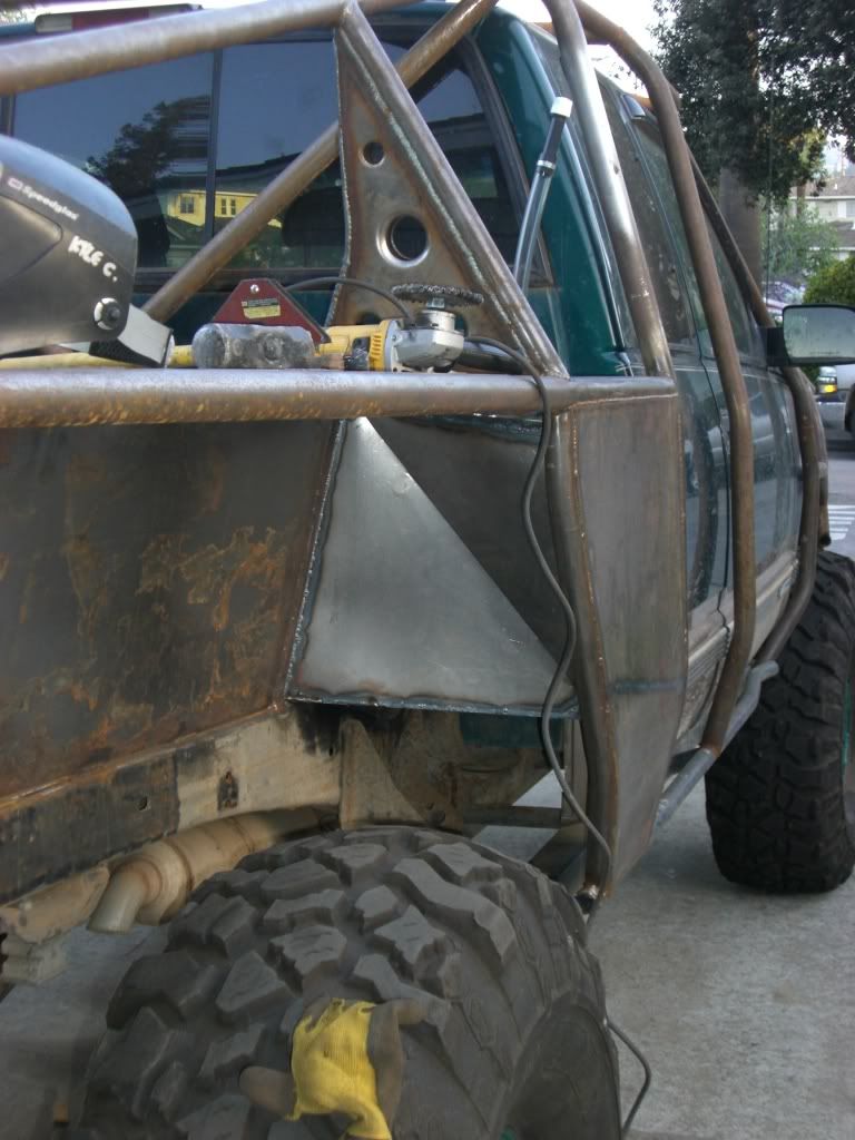
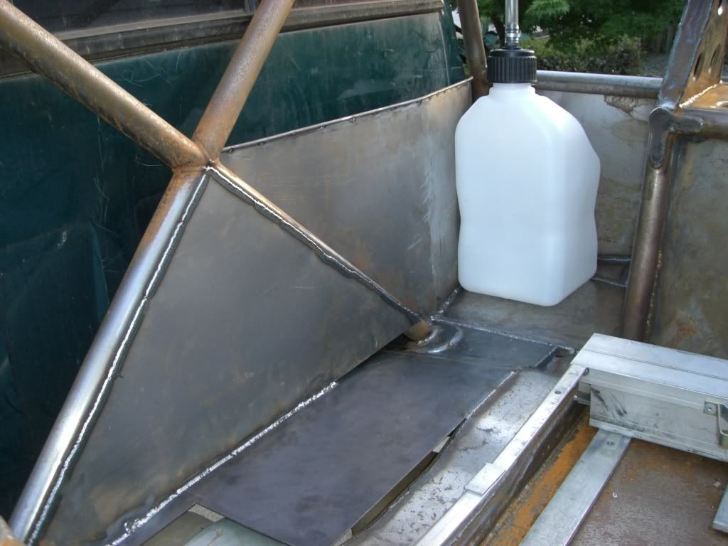
Sometime here I bought a used Can-Bak so I could camp in the truck and being my complete lack of skill with metal hired Mr. Payne to build me some sliders.

PA140005.jpg


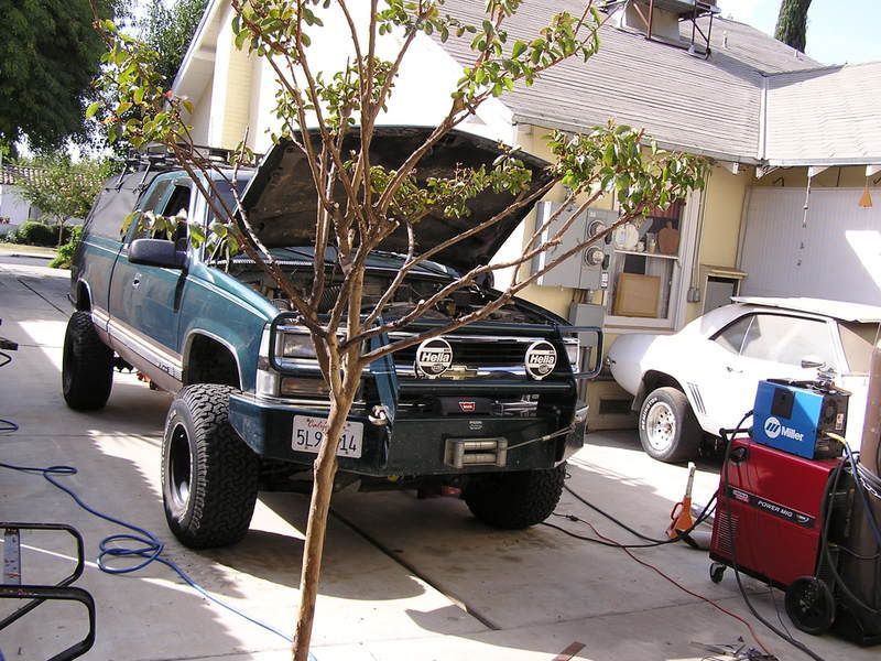
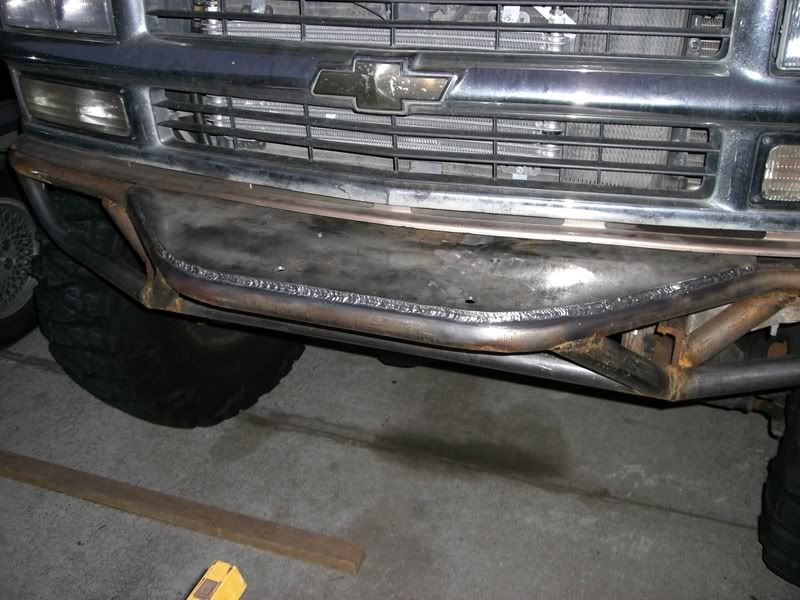
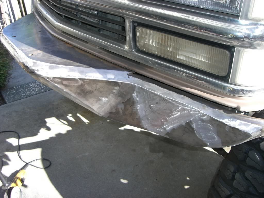
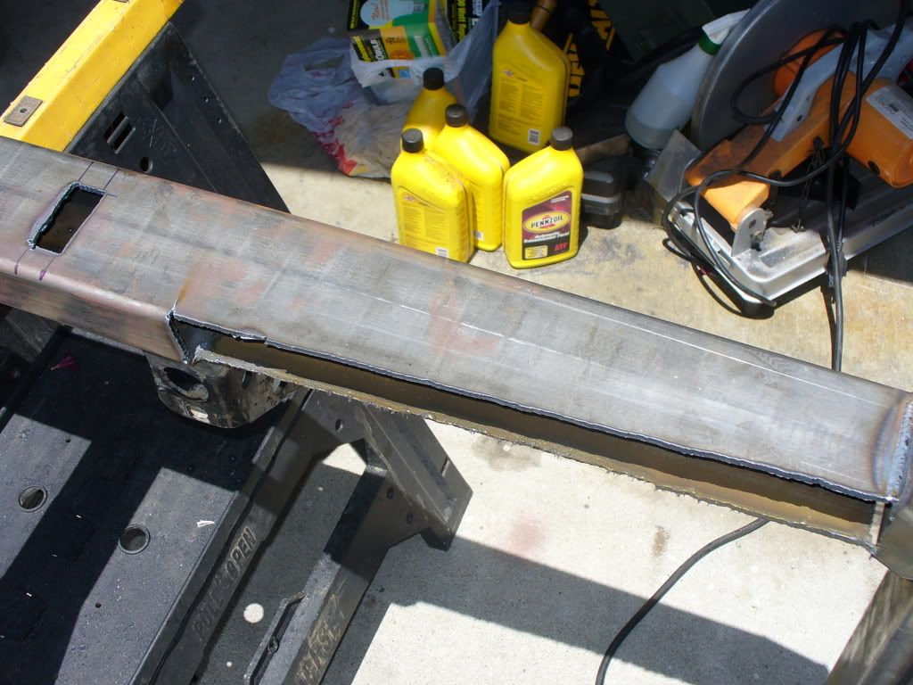
As we were fitting and he was welding them on.

P1160075.jpg

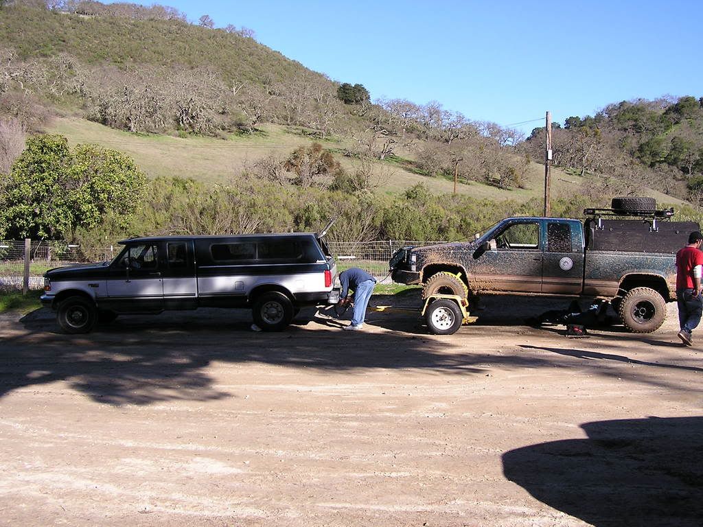
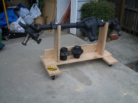
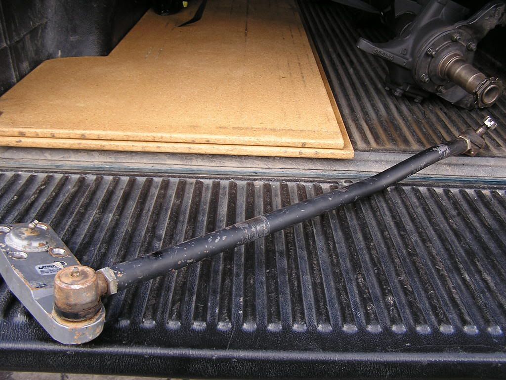
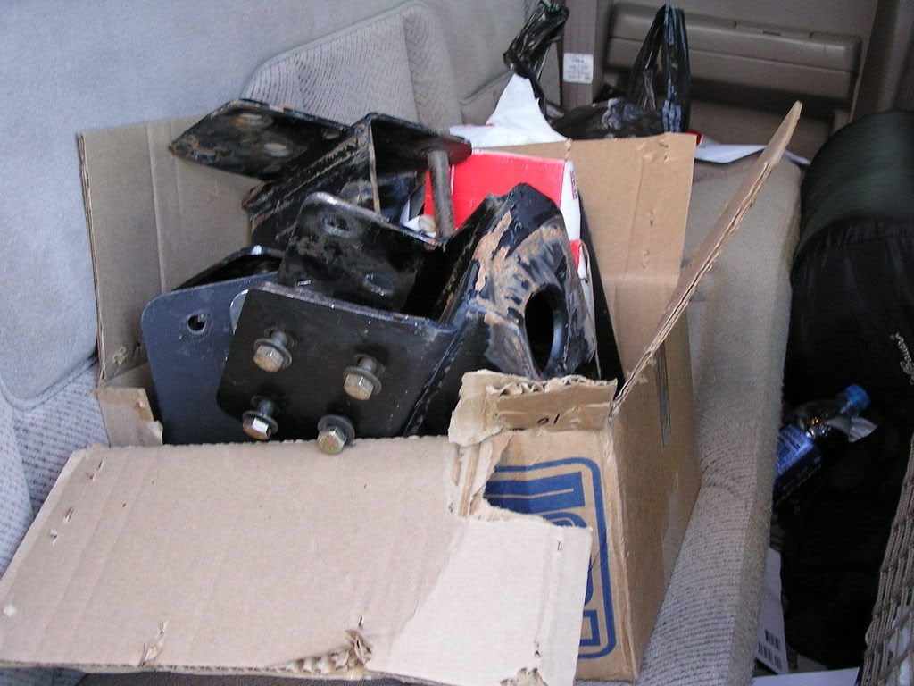
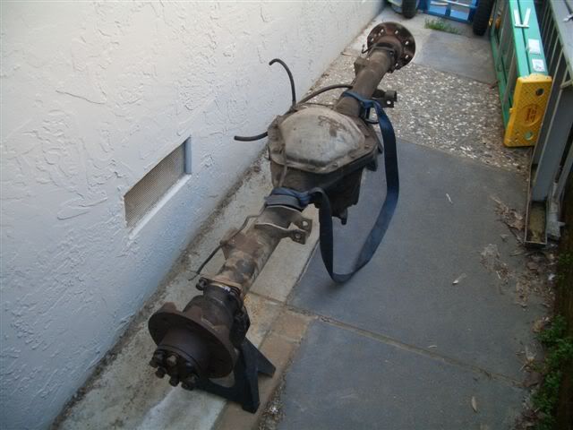
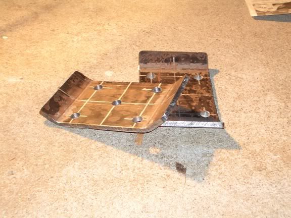
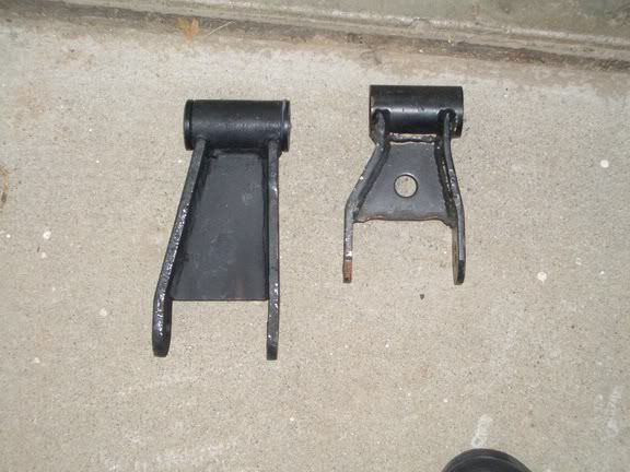
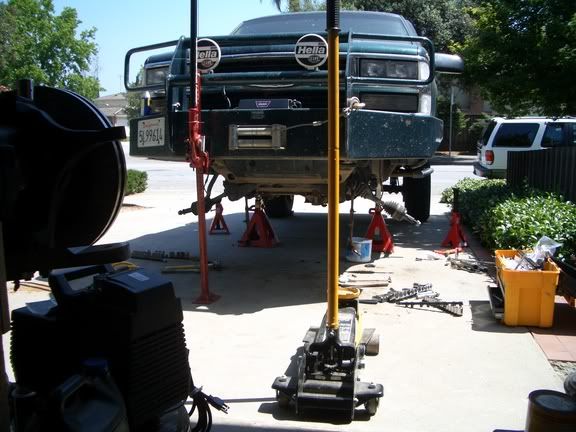
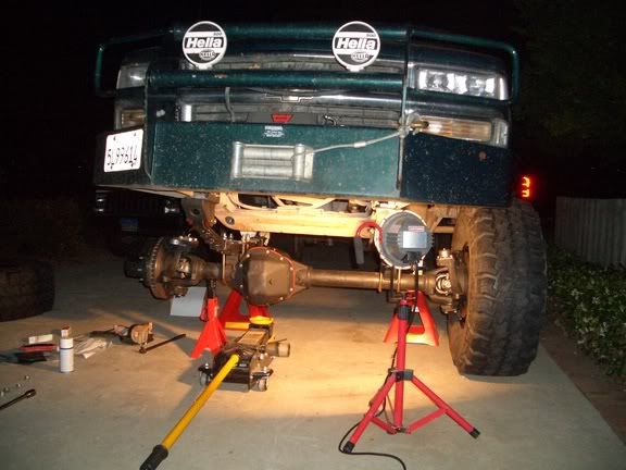
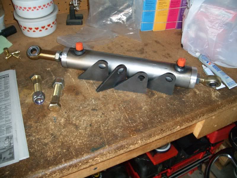
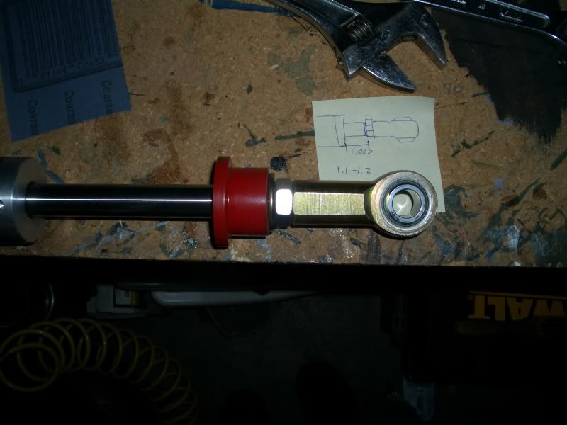
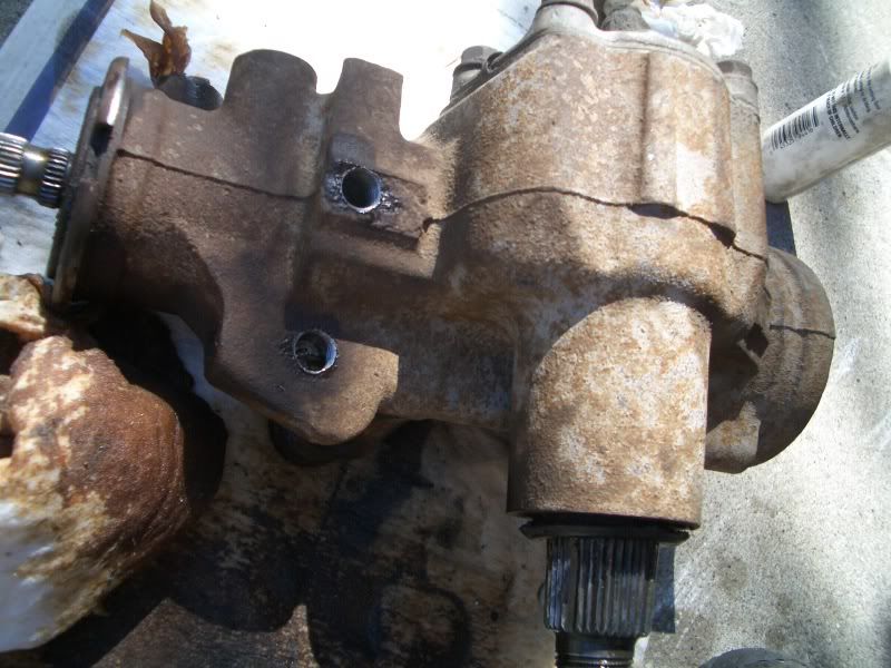
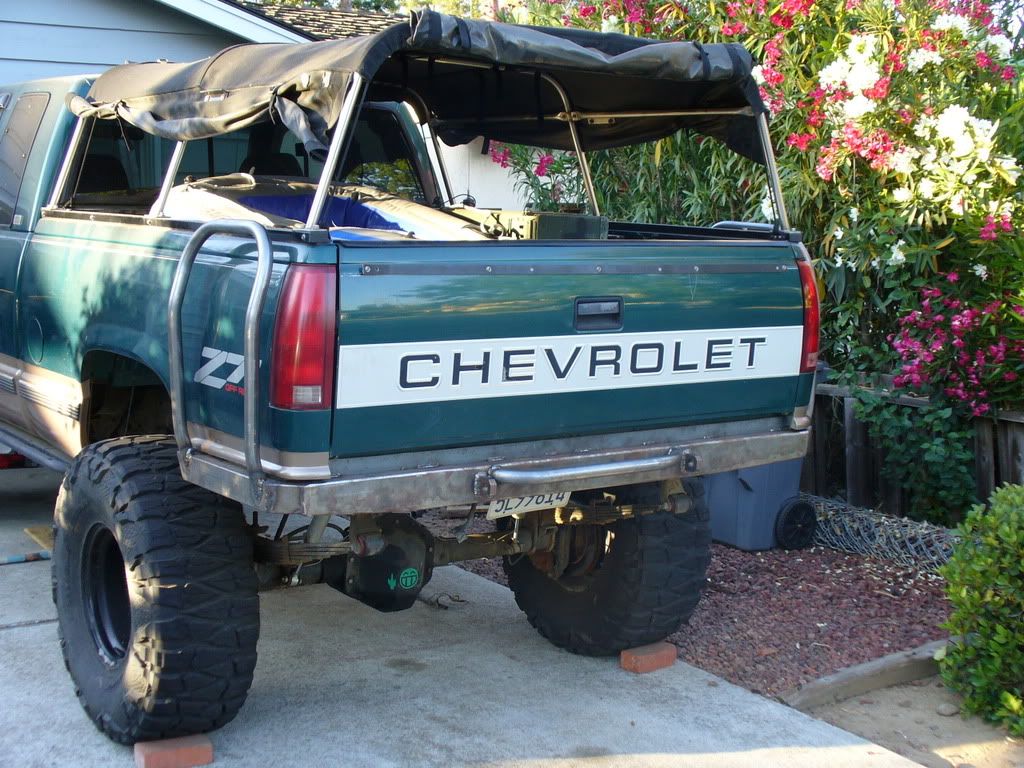
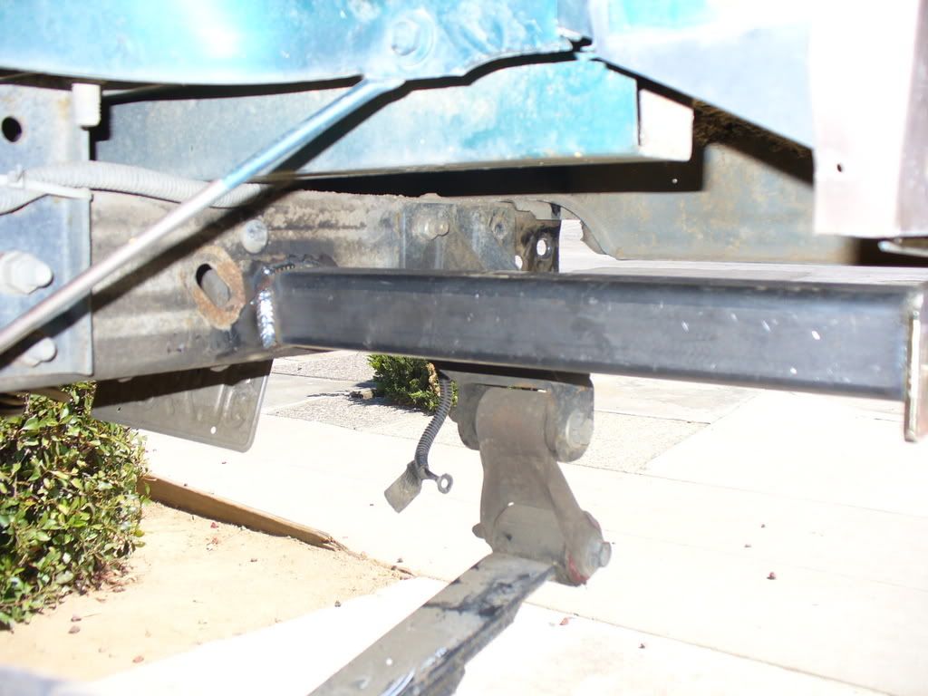
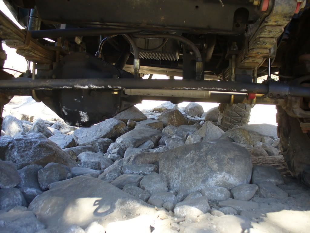
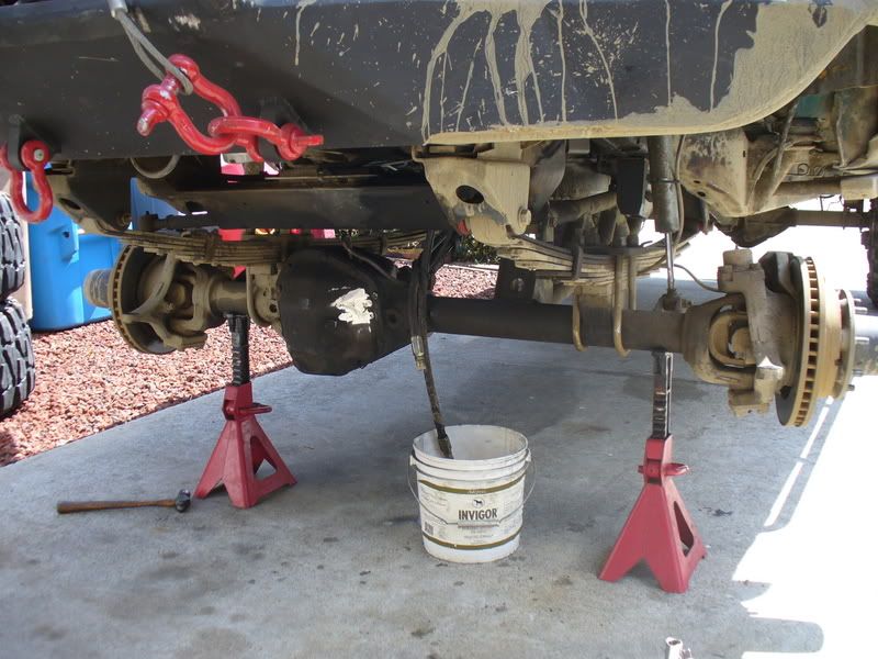
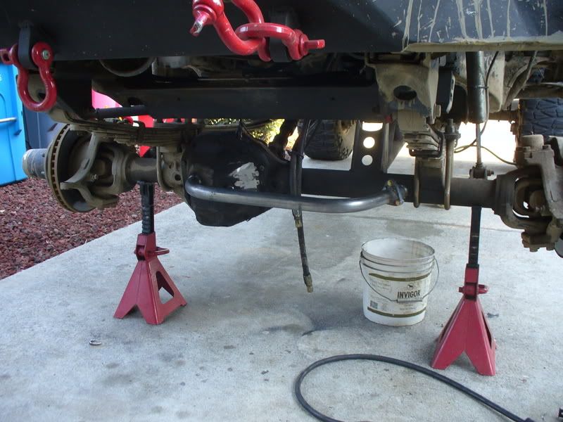
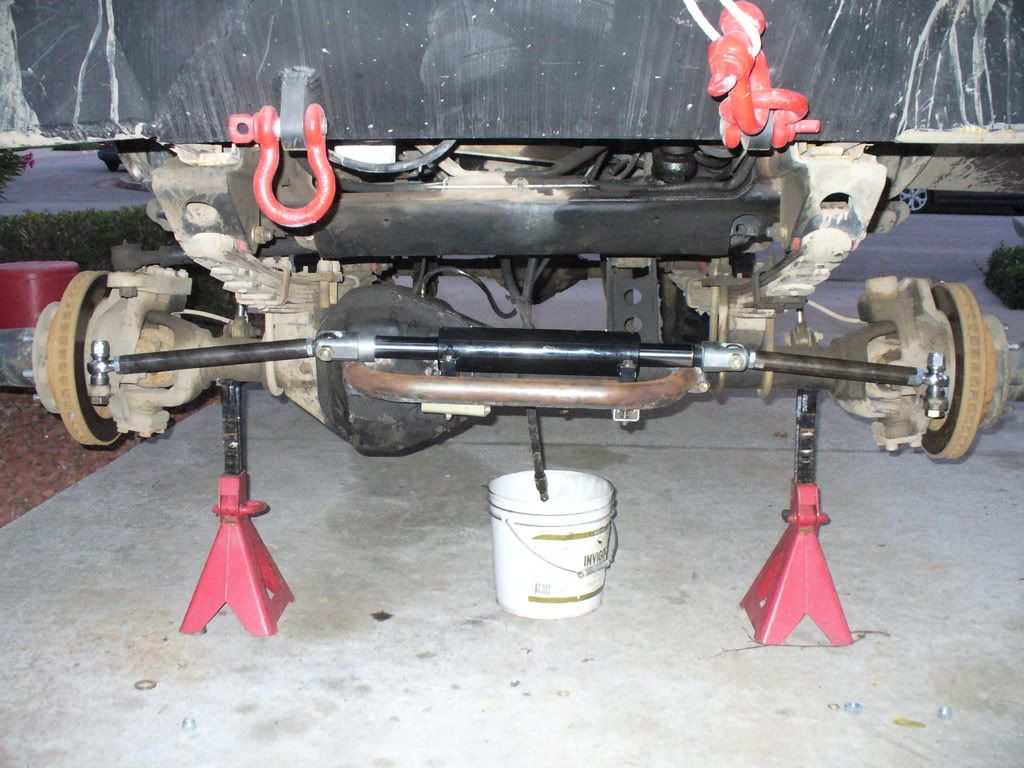
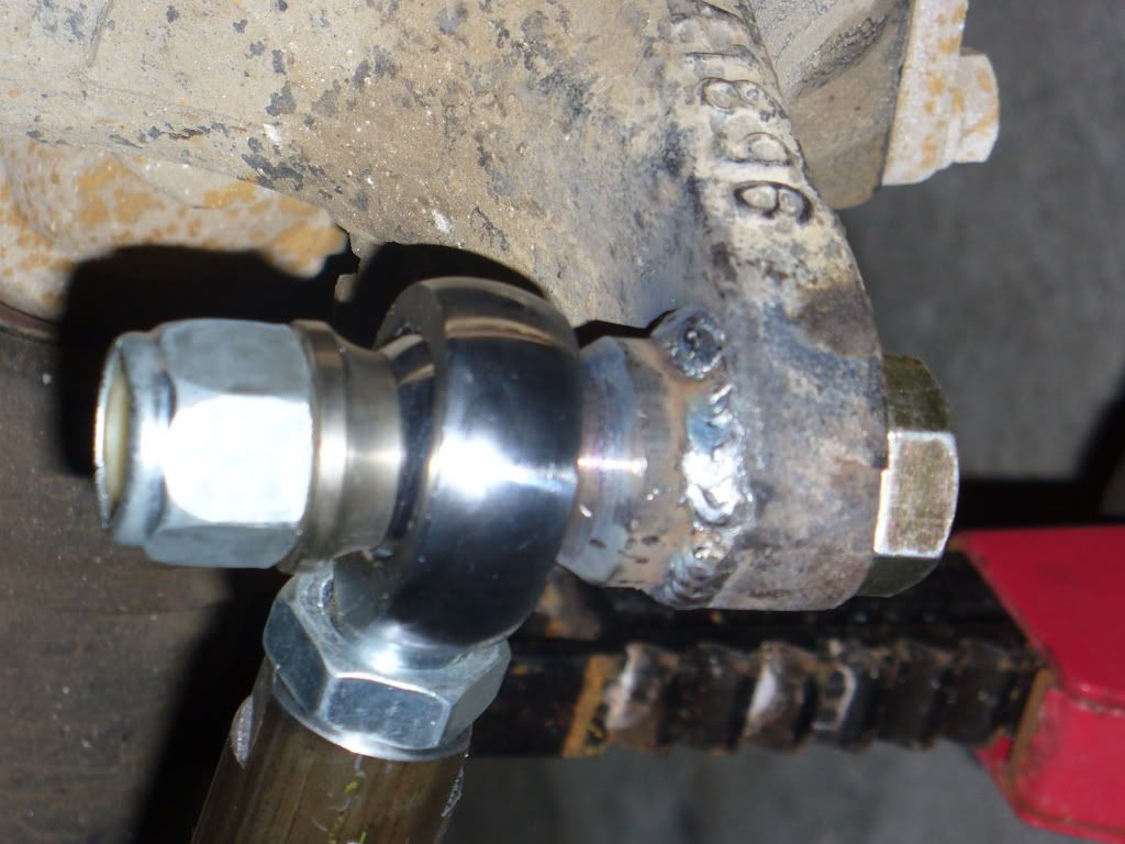
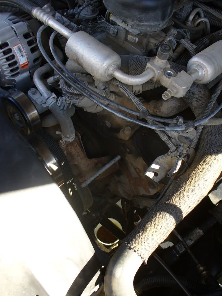
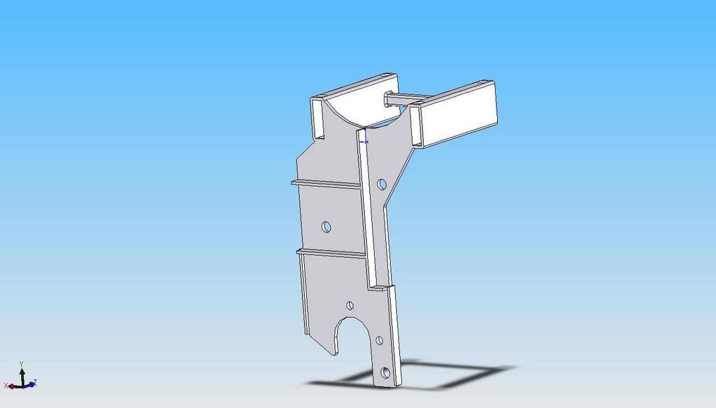
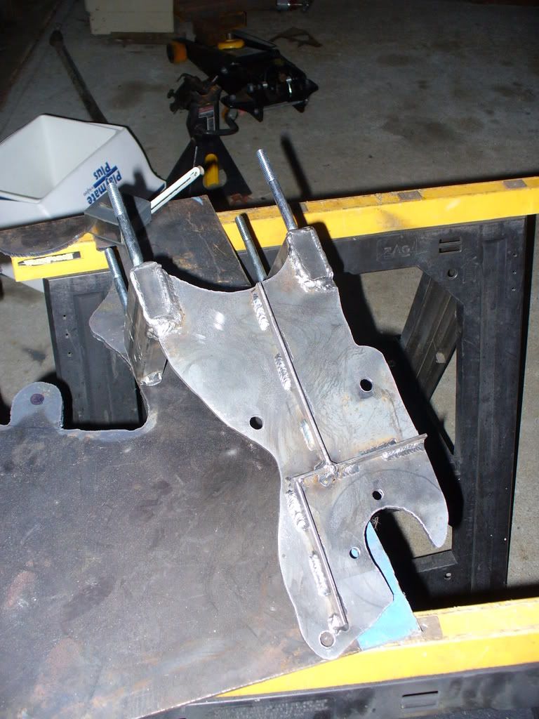
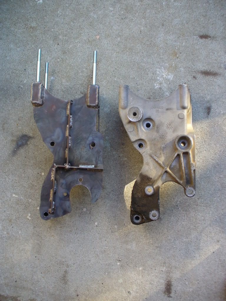
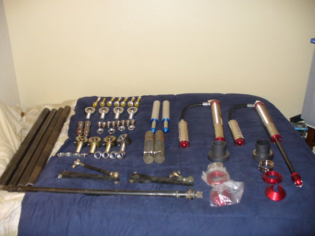
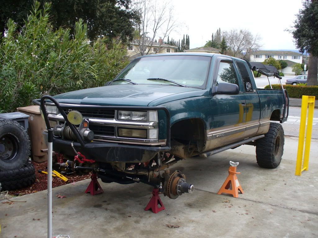
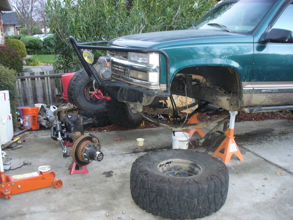
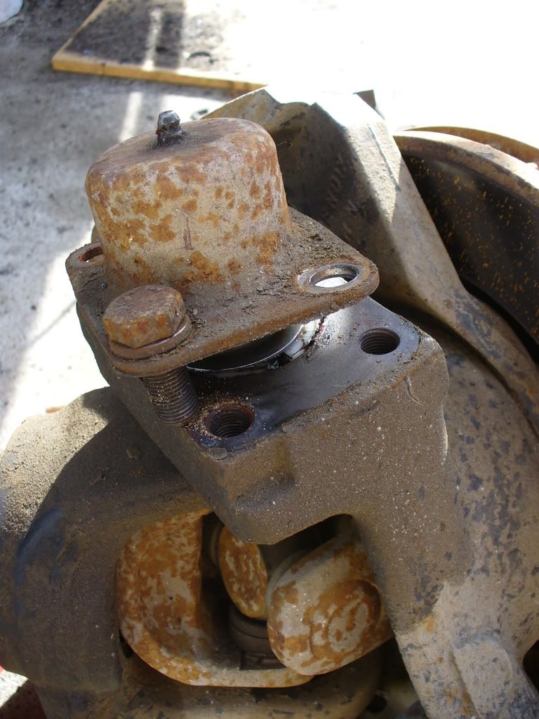
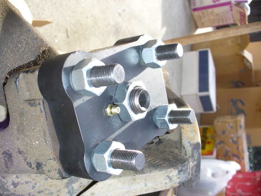
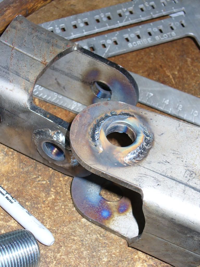
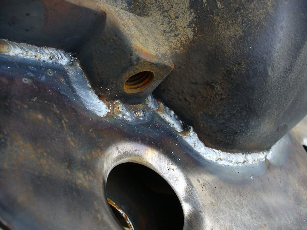
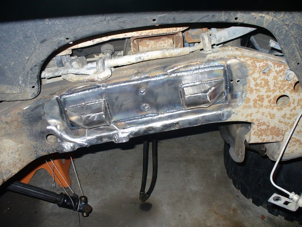
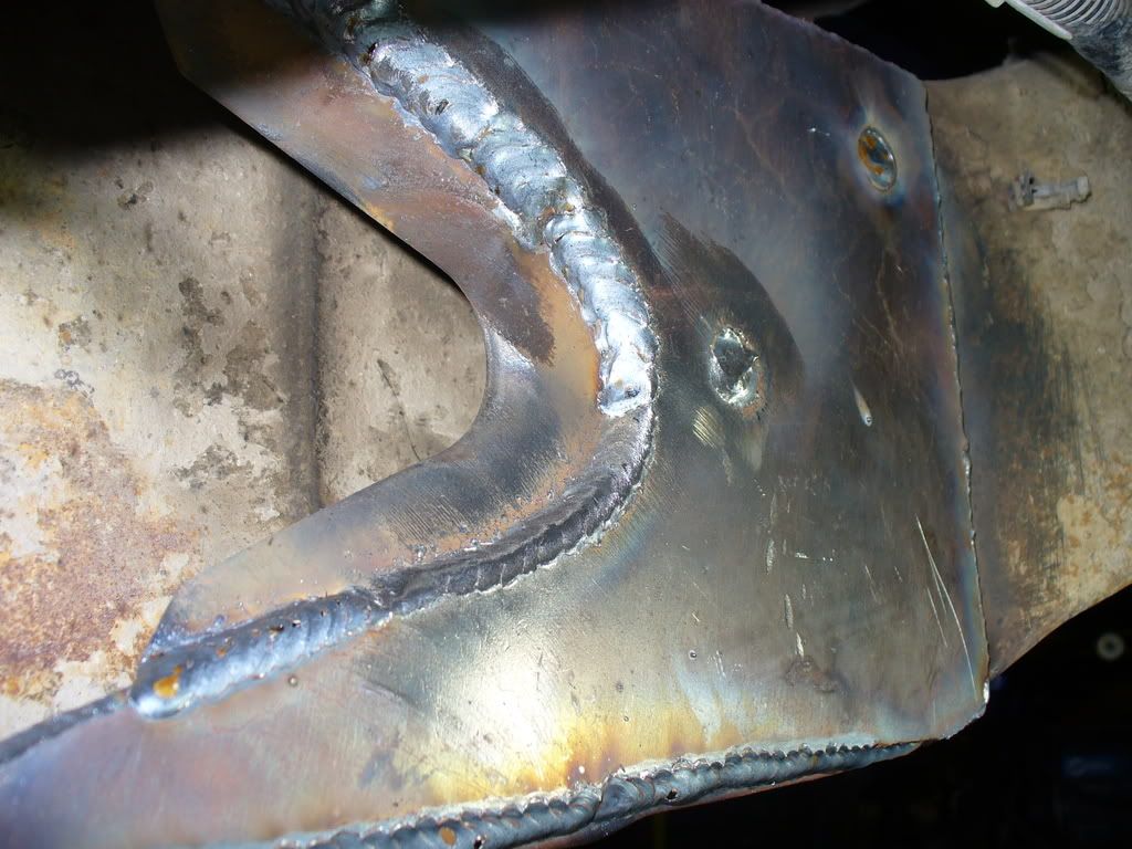
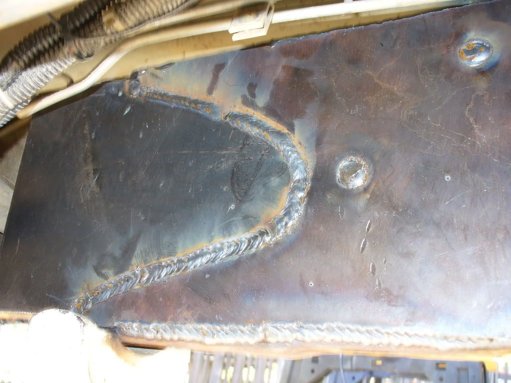
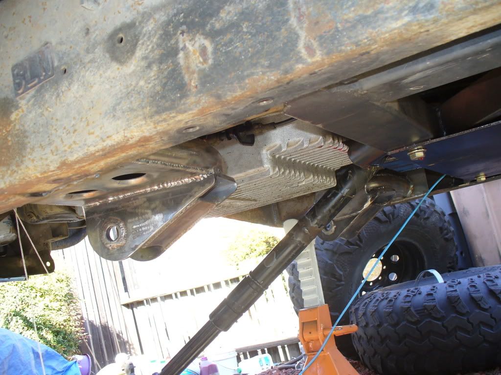
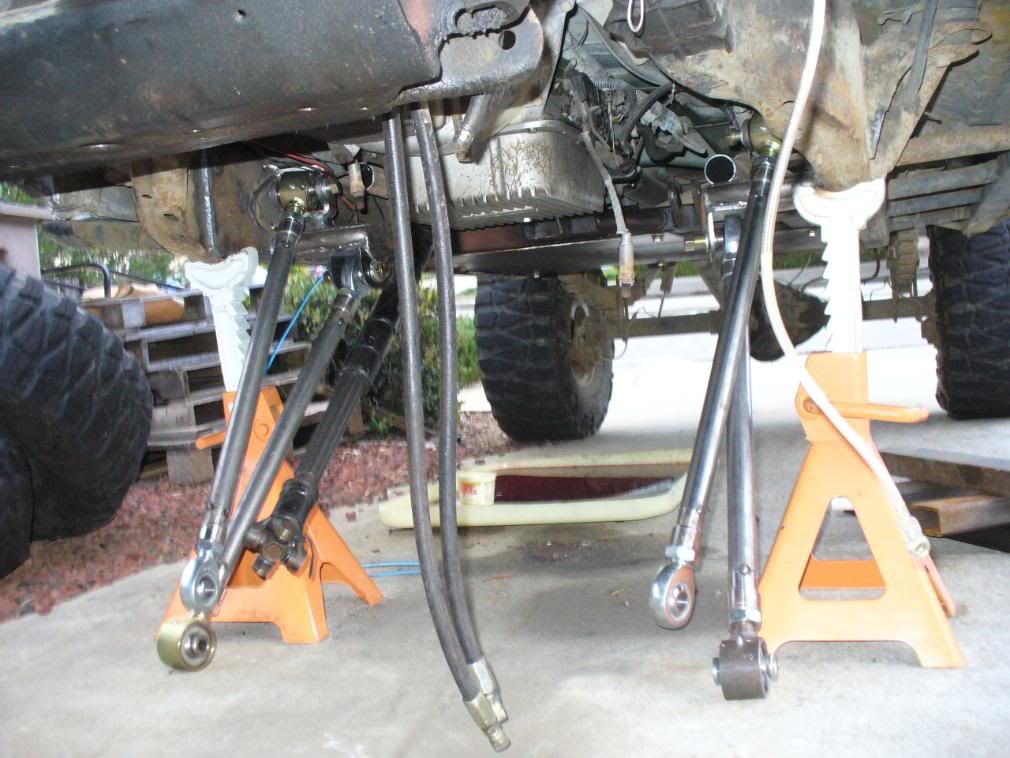
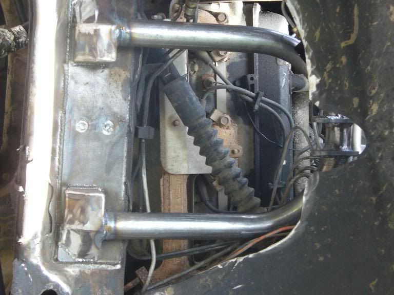
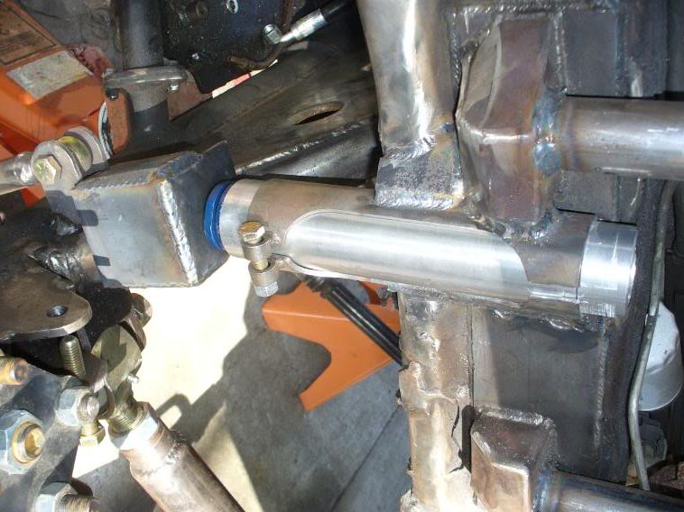
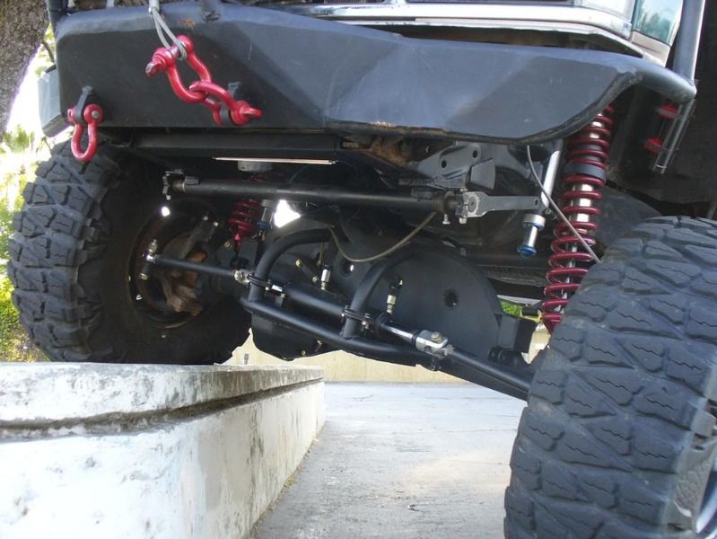
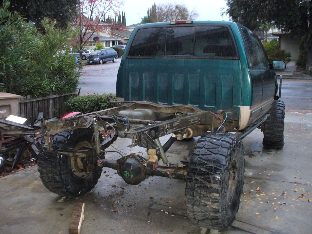
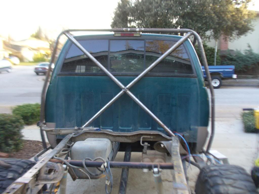
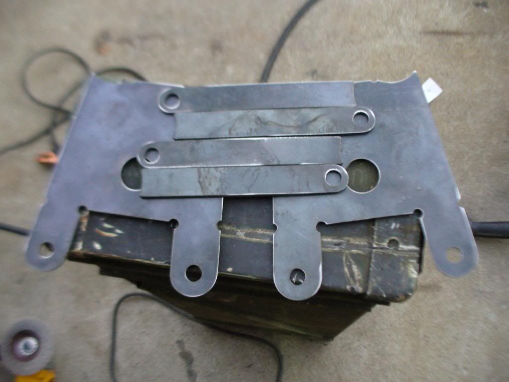
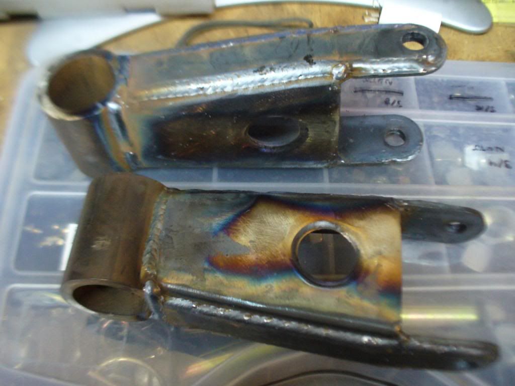
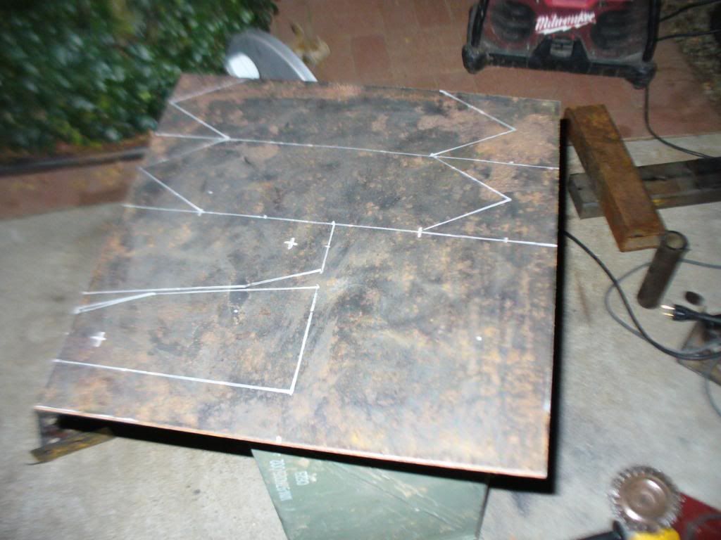
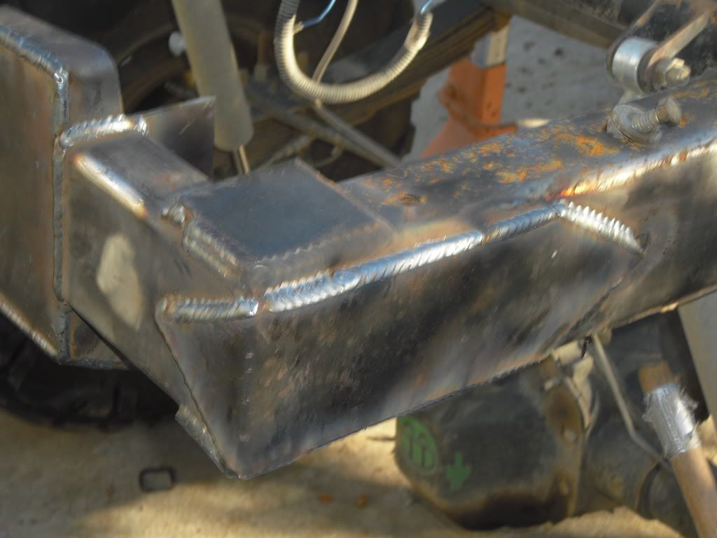
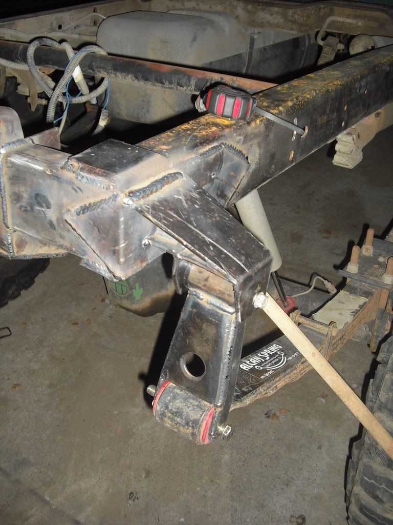
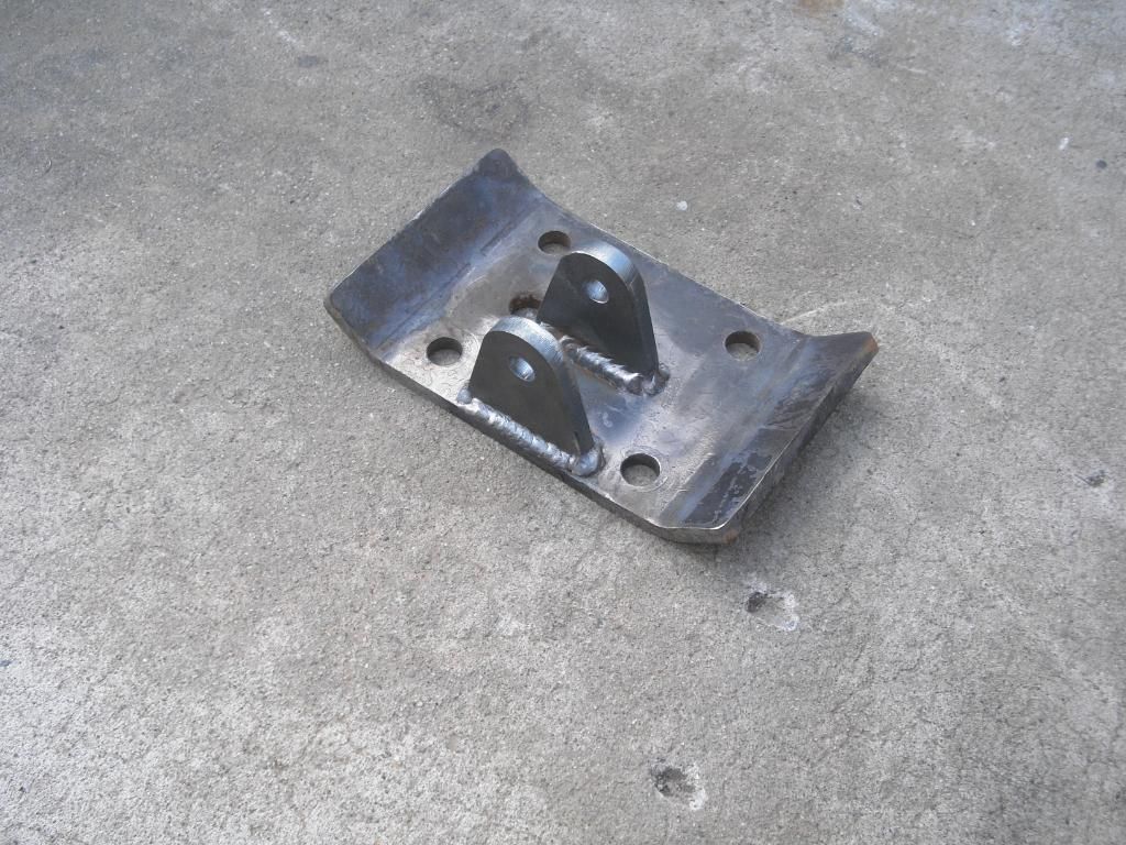
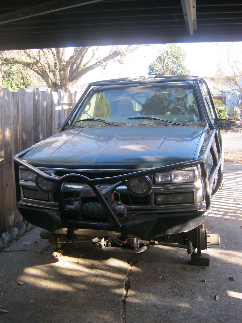
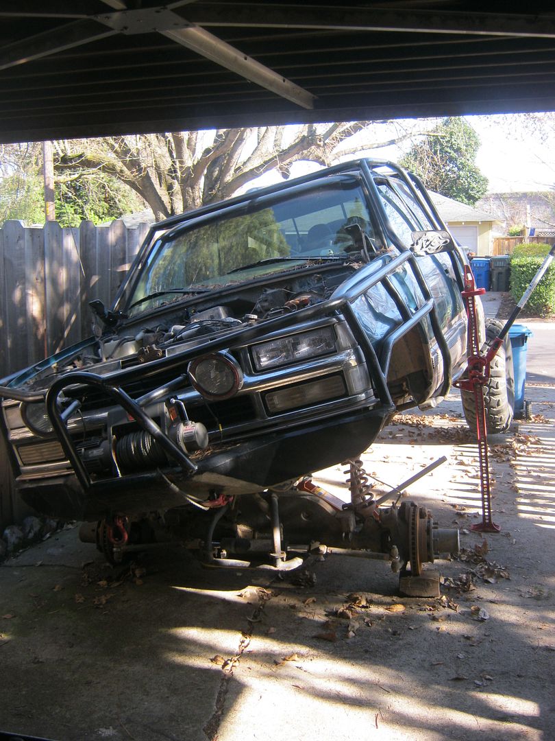
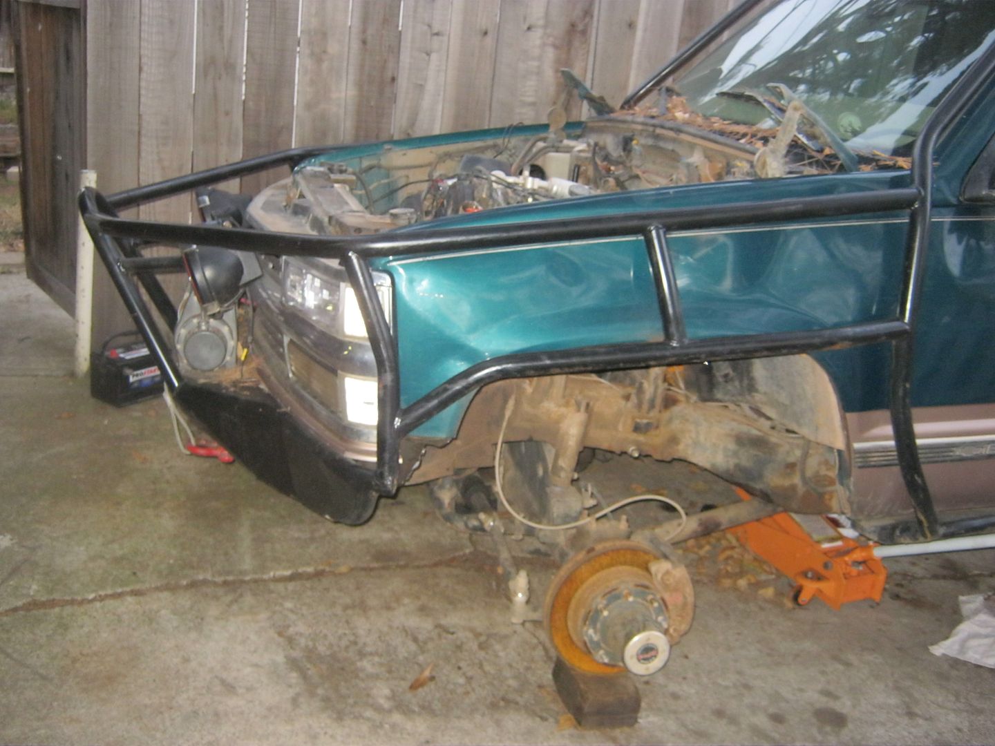
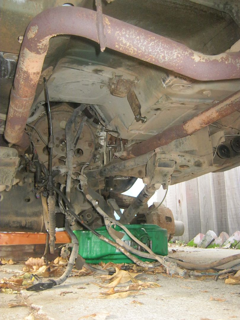
Shortly thereafter I did a shackle flip that Jason sold to me off the cutoff section of his trucks frame and put on some Realift t-bar drop eliminators, which resulted in the situation above. T-bars stripped out the stacked plate adapters and left it on the bump stops, had to call my dad to come pick the truck up. Up to this point I'd been putting front end parts into the truck entirely too regularly. I think I was on the 6th ball joint, 4th TRE, 3rd hub, and everything else once. Jason helped me come up with a solution.
 
Leaf Sprung 1 Ton Swap

So last we left our hero...

Around the campfire the night prior to leaving with my broken down truck, Jason and I hatched a plan to solid axle the Chevy. He had a Chevy 60 leftover from his Willys build he never finished, a set of ORU brackets from his rig before he went to coilovers he needed to get rid of and a crossover steering setup. All I needed was a rear axle, drive shafts, leaf springs, shocks and to figure out how to do it.

CIMG0779.jpg

p1010032.jpg

p1010034.jpg

14FF.jpg


With the main parts in hand I started learning how to tear down and build up axles. 1-2 weekends a month for about 3 months I would go back to the parents house and dig into some tired iron.

Partsboxes.jpg

At some point parts started showing up. 4.88 gears for the front and back, a rear Detroit, ARB for the front, install kits, 1541H axle shafts with 35 spline outers, 806x Spicer u-joints, Warn hubs, kingpin rebuild kits, spindle bearing kits, wheel bearing kits, u-bolt and stud kits, just about everything I needed.
ARBin.jpg

After sweating the housing, washing it down with brake cleaner, I taped off the journals, painted the housing and started learning how to regear a differential.

SpringArch.jpg

I decided that since the goal was performance to alter the kit I had a bit. The ORU kit gives you a pretty ugly shackle angle with 47" stock GM springs. As a result I contacted Alcan spring and ordered a set of 50" long offset center pin 3" lift leaves based on a 47" GM spring. I also had them work up a pair of 3" lift 63" springs for the back. By the time they were loaded the fronts ended up at 52" long, so I had to get Jason to build me a set of longer shackles to bridge the gap.

Update1021.jpg

Update1019.jpg

Update1012.jpg

SYE1015.jpg

All the while Jason was sending 'care' packages to help me get through the endeavor. He was a real life saver.

SYE1012.jpg


I snagged a 241 p-drop out in Madera and tore it down, tossed in a SYE and bolted on a clocking ring.

Truckclean.jpg

K1500019.jpg

Differential2002.jpg

Update12.jpg

The front axle, hangers, steering and springs made it in.

Update17003.jpg

Ryan at WickedFab, who is also sadly no longer with us, burned my perches on for me on the rear axle.

Update24010.jpg

Rear axle snuck in.

Update24001.jpg

Picked up some driveshafts from South Bay driveline. The rear two piece is .134w with 1410 joints and the front was a 1310/1330CV with a 1310 at the pinion. I've been through something like 5 front driveshafts since this picture, but to be short the 1330 CV won't hold the angle and the 1310 pinion joint would munch needle bearings every 18 months or so. 1350 or better everywhere under a heavy fullsize.

P1010038.jpg

Fin, ignore the long haired, bed headed, ugly mug driving.
 
Hydraulic Assist

Following my axle swap I realized that the width of my tires mixed with my new scrub radius and crossover steering made turning the tires while stopped was impossible. As you can imagine a 144” wheelbase that can only steer when moving becomes a bear to do anything with. I decided to go with PSC after hearing good things and I gave Stephen formerly of Expert Offroad a call. Soon after that my ram and mounting kit arrived.
HydroRam001.jpg

I went with a 1.75” bore ram over the more typically 1.5” unit mostly for the increased rod diameter as I had heard a few people complaining about bending the smaller ones.

HydroRam003.jpg

I called MAD4WD up as well and ordered a tube clamp as I wanted to be able to adjust my toe after the ram install and making the tie-rod side removable would let that happen.

Tie-RodClamp002.jpg

With the pieces in I used my newly purchased welder and burned on my diff side mounts. I decided to use the diff cover for a good angle and I knew the cover itself would be fine as I had Jason build me a set as part of my axle build.
[IMG[http://i29.photobucket.com/albums/c299/bggrnchevy/Weldingproject1003.jpg[/IMG]
Then I burned the tabs onto the clamp and mocked it all up.
hydroassistmounted004.jpg


Obviously I had to match the stroke to the throw of the knuckles near exactly to keep from destroying hard parts. To limit the ram I built a stop from a leaf spring bushing I had laying around and a hardened washer.
hydroassistmounted02002.jpg


The box needed to be tapped so I could siphon off fluid and in turn hydraulic pressure. Using Billavista’s tech articles on Pirate4x4.com I located the spots and then drilled the box in the drill press. I then tapped the holes to ¼” NPT. TO clean out the holes I used a magnet and then pumped fluid out the holes by clocking the exits and using compressed air. It seemed to do the trick.
Tappedsteeringbox002.jpg


With this larger displacement of fluid during cycling I put in a larger reservoir. To keep cost down I bought a circle track reservoir from ebay and made it work for my application. I started by mounting the reservoir in the engine bay by welding in a post and attaching it with band clamps.
80e9007.jpg

Then I chopped a barbed adapter down on the lathe.
80e14001.jpg

80e14003.jpg

This piece was then welded to a small plate which was itself welded to the top of the p-pump reservoir.
The reservoirs were then connected with a -10 low pressure hose to effectively make a large reservoir.
hydroassist20005.jpg


To also increase the lifetime of the system I added a filter to pick up the small particles floating in the system. I ordered the filter mount from Summit Racing and used the shorter PH4 filter IIRC.
80e1101.jpg


All that was left was to hook up the box to the ram via the hoses kit I got from PSC. I just cut the lines to length and then assembled the ferule fittings which are reusable and do not require a crimping machine.
hydroassist21.jpg
 
Front Bumper

After a couple trips I came to realize how much my front bumper hurt my approach angle. It was pretty absurd. So after building a hydraulic tubing bender I set to work on my first project, a tube bumper.

Bumper00805.jpg

The main skeleton prior to plating.

BumperPlate01002.jpg

I cut out a winch plate from 1/4" and welded the perimeter to the tubing.

bumper11002.jpg

After much cutting and fitting, and a bit of welding I had the front plated in.

bumper12008.jpg

Some more fill welding and a couple of nights with a flap wheel it was smoothed.

BumperUpdate02004.jpg

I burned some D-ring mounts on to the front plate. I also drilled and tapped the mounds so there welded on the face perimeter and through bolted form the back. Overkill, but I felt better about it. I also burned in a 2x2 spar between the mounting points and 2 more uprights to tie the back of the inch plate into the mounts.

misc01005.jpg

Done.
 
Rear Bumper

RearBumpercut02.jpg

While I was at making my approach angle better, I decided the rear left a lot to be desired as well.

RearBumpercut002.jpg

Ruh roh.

RearBumpercut004.jpg

Now you did it.

Rearbumper05.jpg

Rearbumper03-1.jpg

RearBumper5-1.jpg

Bumper6.jpg

MetalWork1.2001.jpg
 
4l80e Swap and Rebuild

Previous to this my 4l60e burned up slipping right through the 3-4 clutch pack on my way home from a trip to Pismo. I swapped in a 4l80e, which I also burned up in about 6 months. As a result I pulled the 80e and built it up a bit and made sure it was clean and my end play was solid for years of good running.

80e1.jpg

The donor, a 95 4l80e from a project truck that got parted and the 241 came with.

80e2.jpg

Already sporting a 3+ qt pan.

241internals.jpg

I needed to swap the input from the 90 V20 Suburban 241 (32 spline, thin bearing) into the 241 I was running out of a K5 to mate to the new tranny so some disassembly was in order.

80eswappics3002.jpg

The 60e came out in spectacular fashion.

80eswap6.jpg

I spliced two wires on the tranny harness so the 80e would work.

80eswap7003.jpg

Put the tranny and t-case in.

80e9002.jpg

A belly pan was built that replaces both factory cross members and was skinned in a bolt on piece of 6ga AR plate and itself bolts into 4 sets of tabs welded to the bottom lip and inside of the frame rails.

A 40k gvwr Tru-Cool heat exchanger was added as well as an external filter on the cooler return. Other than that I just wired in the turbine input speed sensor to the PCM and it worked fine for a couple of months. Rebuild time.

Transpartsv201.jpg

On the list of parts was a rebuilt BU42 converter, low stall to be used with the 6.5TD and the 454. In hindsight, this was a bad idea. Works great for crawling, but doesn't let the motor wind up so 4hi is a dog. Future installment will correct this.

Transpartsv201-2.jpg

Among other upgrades I went with Raybestos blue plates for the OD pack and a Borg Warner reverse band (non-kevlar).

TransmissionPartsV201-2.jpg

Red alto clutches for all other packs, with new steels.

TransDrop1-1.jpg

Popped the tranny out.

Tranny02-1.jpg

Tore it down.

Tranny02-6.jpg

Tranny02-10.jpg

Tranny02-11.jpg

Tranny02-8.jpg

Tranny02-9.jpg

ODrollerclutchmix.jpg

Found a bunch of broken stuff.

Tranny03.4001.jpg

Replaced all the soft parts, a couple hard parts and put it back together making sure to set/verify end play for the input and outputs.

Tranny03.6001.jpg

Plugged it back in and promptly turned the truck around in the driveway to signal victory.
 
Double Ended Steering Ram

I ran the single ended (SE) ram I put on previously in this thread for while. I had good luck with it general but with the ARB locked in and lots of turning for my wheelbase I managed to heat the system up enough to get cavitation from the pump and leak fluid everywhere. Add the fact that I was running my tie-rod into everything and it was a system that wasn’t going to last.

Rubicon07147.jpg


Poor 1-1/2” .375 wall tie-rod, bent again.

Thinking I was intelligent I thought about putting in a double ended (DE) ram to replace it. That would allow me to keep low steer (so I don’t have to worry about knuckle breakage) and protect my ram. It also gives me more surface area for the fluid to work on so I get more effective steering force. Well I propose this to Jason, which I’m thinking is a little unique in an assist application, who in turn says he did the same thing back when he had leafs and loved it. Damn guy was always 6-7 steps ahead.

Well I ordered up my ram in a 2.5” x 8” with a 1.5” rod variety.

DEHydroAssist01.1002.jpg

DEHydroAssist01.1001.jpg


I also picked up the tube for the MRTs.

DEHydroAssist01.1003.jpg


At the time I was planning to mill some clevises to hold the mini tie-rod ends (MRTs) that I had drawn up in Solidworks, however the mill we have wasn’t up to the task of regular CR 1020 mild steel. I guess it is just going to have to stick with aluminum and plastic.

Instead I bought a set from Sean at POS with hardware. I also ordered some of my hydraulic hose and fittings.

DEHydroAssist01.4.jpg

DEHydroAssist01.5003.jpg


For rod ends I went with fairly cheap ¾ x ¾ chromoly 1 piece units. We’ll have to see how long they last without slop.

DEHydroAssist01.3002.jpg


I started by removing the ram and its old mount along with the tie-rod. Comparing the two seems like apples and oranges.

DEHydroAssist01.6002.jpg

DEHydroAssist01.6003.jpg


Using my tube bender I made the hoop for the ram mount. As part of the mount I had to add a disconnect for the driver side being the passenger side is mounted to the diff cover.

DEHydroAssist01.6004.jpg


DEHydroAssist01.6005.jpg

I burned out the mounting plate for the ram with the handy dandy plasma cutter.

DEHydroAssist01.6006.jpg

In order to mount the ram so the clevises clear the tube I had to chop and turn some spacers. I did this out of a length of DOM I bought for the task.

DEHydroAssist01.8001.jpg

I also cut down the MRT tube and bored the ends out and tapped it to ¾-16 for the rod ends. In addition I used the mill at work to put flats on the tube. It took a while but if I made light passes it held consistency.

DEHydroAssist02.2004.jpg

The ram mount is off center by and inch as a result of diff cover clearance. As such the MRT’s are different lengths. This hurts the ackerman angle but with the design it wasn’t going to be perfect anyways.

DEHydroAssist024001.jpg

For my pump, I needed some more flow to keep up with the large swept volume of the ram. I started by going with the cast iron KRC pump which flows 3.7gpm with an E valve, unfortunately I’d have to sacrifice flow at low rpm to keep up with the high rpm so as to not hurt the pump. The aluminum KRC pump though is rated to handle higher rpm’s so I can run a smaller pulley and keep low rpm flow. The only problem is with an E valve (the largest) it makes a lower 3.2gpm. I still decided the aluminum pump was th way to go.

DEHydroAssist01.9004.jpg

Aluminum E flow valve.

DEHydroAssist02.2002.jpg

With a higher flow pump, moving more, higher pressure fluid it was time for a PS specific cooler. The stacked plate style transmission cooler I was using just doesn’t flow enough fluid and I don’t think it was large enough. I decided to try a different style. This unit is all aluminum, has large 3/8” NPT ports on each end and holds a very large volume comparatively. The large amount of fins to increase the surface area should work well to cool at low speed as well as high.

DEHydroAssist02.3002.jpg

Here you can see the internal fins to help pull heat from the fluid more efficiently and transfer it to the aluminum body and in turn the air.

DEHydroAssist02.3003.jpg

To give the MRTs plenty of misalignment as well as raise them up a little alleviate the angle at lock I put a misalignment spacer I bought from Ballistic Fab and a turned piece of DOM on the bottom. I preheated the cast knuckle, welded the joint and then heated it again to keep the different expansion and contraction rates least noticeable and then peened the weld to alleviate stresses while cooling. The end result is ugly but much stronger.

DEHydroAssist024004.jpg


It then came time to figure out the mounting of the pump. I pulled out the stock bracket which also mounts the AC compressor.

DEHydroAssist025001.jpg


I modeled the new bracket I had to build in Solidworks to help me visualize and brainstorm. It is amazingly handy to be able to virtually build something before you have to do it physically. It saves immeasurable amounts of time.

KRCbracket.jpg


I started fabbing and it progressed as I had time in the evenings.

DEHydroAssist026002.jpg

DEHydroAssist028001.jpg

DEHydroAssist028002.jpg


I finished it that weekend with welding on the spacers and the runners for rigidity.
 
DEHydroAssist028008.jpg


I finally bolted it all in and added the AC compressor and the KRC pump. Do to the tight squeeze they both had to be added after the bracket was bolted in and it was quite the tight squeeze for my knuckles.

DEHydroAssist030002.jpg


I installed the cooler under the radiator behind the protection of the bumper. It cuts down on air flow but more importantly is the safety of the cooler as it is part of a pressurized system.

DEHydroAssist027002.jpg


I received the Appleton cooler/filter reservoir(CFR). This unit, as the name suggests it has an integral filter as well as a finned reserovoir to aid in cooling.

DEHydroAssist029001.jpg


I painted the ram mount, ram and MRTs and got them installed and the tires back on.

DEHydroAssist035001.jpg


I found one of the belts used on Jeep 4.0L motors was the right length for my application with the right number of ribs after a bit of work. With that I got it working.

[yt]3PU_-JFDQEY[/yt]

At this point the only thing I’d change is the pump. Even after all that work on the bracket I might go back to a p-pump. I have adequate flow just over idle but at idle it is very slow. Sean at POS talked with me for a while describing his uniquely built version that puts out a ridiculous 6.5gpm while remaining cool enough for longevity. He stated in early 2008 he was hoping to step up production in order to drop cost significantly.
 
Triangulated 4-Link

After running the leaf springs for a while I started to find myself limited. I couldn't run a bigger tire without going taller as I was limited on my axle placement, the low rate springs give a lot of roll, approach angle is still pretty bad and because I was running both a LP front diff and the rear shackle leafs springs the pinion would swing down at droop and make my front driveshaft angle awful. I began to hatch another plan.

Link011001-1.jpg

Parts.

Link015001.jpg

Admitting the patient to surgery.

Link015007.jpg

Operation in progress.

Link018001.jpg

Link018009.jpg

Upper kingpins were changed to springless and since I was going to full hydraulic steering at this point neither has an arm.

Link019005.jpg

Weld washers were added to all 1/4" backets to increase bearing surface and limit the wear should the bolts every come loose.

Link024001.jpg

A truss was bent up and notched, the webbing was cut from premium grade cardboard and permanently fastened with high grade painters tape.

Link024007.jpg

Maybe not.

Link028007.jpg

The plates were burned onto the whole axle, including the casting using as much pre and post heat as I could muster.

Link043001.jpg

Cleaned the frame rails and burned on some hoop mounts.

Link039010.jpg

Link040001.jpg

Support plates were burned onto the inside of the frame rails.

Link042005.jpg

Link mounts were created form some brackets and adapter pieces and burned in.

Link04.jpg

Mockup links using 1-1/2" HREW tack welded to the ends of the tube adapters.

Link04-20.jpg

Link04-19.jpg

Upper and lowers were welded in using a fillet and a couple of rosettes. Upper links are 2" .250w DOM, lowers 2.25" .375w DOM. The uppers could have been made form 1-3/4" .120 in retrospect and the lowers from 2" .250w 4130 to save some weight.

Link04-27.jpg

Hoops went in.

Link05-12.jpg

Bumps tops and their landing pads were welded in.

Link06-21.jpg

Engine hoop was added.

Link06-26.jpg

All bolted together.

Link07-10.jpg

It lives again!
 
Double Ended Full Hydraulic Steering with Two Pumps

With the conversion to a triangulated 4 link I had to remove the crossover aspect and mechanical linkage in my steering. In addition I wanted the tires to turn faster, so I need more flow which I decided I'd solve best by adding a second PS pump.

Link04-28.jpg

A key aspect to this conversion is the deletion of the steering gear and the replacement with a steering valve, commonly called an orbital valve. The factory steering gear only outputs pump pressure when it gets mechanical resistance on the linkage so without a linkage hooked up it's useless.

Link04-32.jpg

Mounting the valve simply required me to remove the box, clean the area and burn the mount on. Bolting the intermediate shaft to the new valve though required a miniature column to adapt it.

hydraulicreservoirfront-1.jpg

I drew up a larger reservoir to happily supply both pumps.

Link05-16.jpg

I cut the parts out of some sheet, burned them together and tested it for leaks.

Link05-11.jpg

I built a flange style lid and welded some cap screws in as studs.

Link05-7.jpg

With an internal filter, sight tube, dual outputs and an inlet with a vent fill cap and some paint it was done.

dualpumpassemblyiso-1.jpg

I also kicked out a design for the bracket to mount both pumps.

Link06-12.jpg

Pacific Fabrication shot the main plate out for me on their CNC plasma table.

Link06-14.jpg

I turned some standoffs on the lathe, welded them, the mounting tubes for the compressor and the support tubes in.

Link06-22.jpg

I did a dry fit, made up all my lines with check valves post pump outputs and T-ed them together to the steering valve.

Link07-7.jpg

Painted, with a modified P-pump clocking. The output was too close to the exhaust manifold for my liking.

Link07-4.jpg

Installed with the very long belt routed.

[yt] bRTVwqUo6jY[/yt]
Huge speed improvement over the last pump setup.
 
Exoskeleton and Tube Bed

After smashing in the driver rear cab corner and breaking out the extended cab window I think I realized the snowball that was mounting. I needed to build a cage to rub on or I needed to stop wheeling in the fashion I was. Whatever to do:p

TurkeyDay056.jpg

200ft of 1-3/4" DOM and HREW.

Cage02002.jpg

Bed removed.

image1.jpg

Rear winch mount/crossmember, shackle flip and shackles designed.

Cage04003.jpg

Geoff loaded up with the old bed.

Cage04009.jpg

Hoops bent up.

cage11001.jpg

Bracing welded in using fish plates on the frame.

cage13001.jpg

Winch box laid out.

cage13003.jpg

Winch box fitted, bent and welded.

cage14001.jpg

Shackles shot out on the plasma table.

cage14002.jpg

Bent, fitted, welded.

cage15004.jpg

Shackle flip and frame plates marked.

cage16001.jpg

cage16003.jpg

System built.

cage16004.jpg

Front end coming together.

cage17007.jpg

Rear tubes dropped.

cage17005.jpg

Roof bent and notched.
 
cage18001.jpg

Coming together.

cage20002.jpg

Floor welded in.

cage21011.jpg

Plating in the bed.

cage21009.jpg

Tail light housings taking shape.

cage21007.jpg

Fitting more panels.

cage23004.jpg

Bulkheads shot out, dimpled and welded.

cage27001.jpg

Fender plates welded in after drilling and dimpling a lot of holes.

cage30006.jpg

Bed slide mockup.

cage29001.jpg

HMMWV 8 bolt double bead lock wheels.

cage30004.jpg

Runflats were cut down on the vertical bandsaw.

cage32003.jpg

cage32001.jpg

New press formed wheel centers and rock rings arrived.

cage33001.jpg

I cut out the centers using the plasma and then dropped the new center in and tacked them. I then bolted the wheels on to the hub and using the fixed tubing attached a dial indicator and beat the axial and radial runout into under .020.

cage34003.jpg

Tin work in full swing.

cage34002.jpg

I welded 1/4" CR rod to the exposed edge of the sheet to add some rigidity and break the sharp edge.

cage34001.jpg

I left an access panel for the fuel pump.

cage40001.jpg

After entirely too much sanding to remove all the rust.
 
cage40002.jpg

She got a nice coat of primer and then a gloss black finish.

cage41002.jpg

Wired up the tailghts.

CIMG7735.jpg

Built a mount for the spare fuel can.

CIMG7738.jpg

CO2 tank mount.

CIMG7749.jpg

Modified the slide to fit my assorted boxes.

CIMG7757.jpg

Works well.

shockmountiso.jpg

After using it very briefly I noticed I needed more damping out back so I had to design a mount for a bigger shock with some more travel.

cage27003-1.jpg

Pac Fab shot out the plate work for me and I bent it up at their shop. I fixutred the parts and burned them together.

cage26003.jpg

The bed sides I so carefully built were carved open.

cage27005.jpg

New mounts were welded in.

cage26006.jpg

Tabs were added to the spring plates.

SHOCK103.jpg

Shocks were mounted.

CIMG7907.jpg

All done and getting used.
 
Interior Cage

After building the exterior cage I quickly came to the realization that I needed to do something about occupant safety. Speeds were up, and I was more willing to do dumb things, except I was still being held in by a factory 3 point belt.

101_0090.jpg

I procured 3 seats and 3 harnesses.

101_0089.jpg

Removed the factory seats, belts and console.

101_0092.jpg

Seating mockup.

101_0095.jpg

I started welding in the fish plates and slider mount tubes.

08_23_10024.jpg

08_23_10026.jpg

The internal mounting cage came together quickly.

08_24_10003.jpg

With a pile of tabs and tube caps I got to work welding everything up.

101_0055.jpg

Forward.

101_0053.jpg

Back.

101_0075.jpg

Bent and welded shoulder harness mounting bars.

101_0076.jpg

Painted the tube work.

000_0001.jpg

Fought with the carpet until it would stay in place.

000_0004.jpg

All done again.
 
Now that we're up to speed on past projects and incarnations, how about the current transition.

LQ9 Swap

Misc020.jpg


The poor rig works well, but the engine has 165k miles on it and didn't have a lot of power to start with. Combine that with a low stall converter, slightly steep axle gearing an 80e 2.48:1 1st and it's just not cutting it.

Misc022.jpg

Enter the VIN and piston verified LQ9 that's being prepped to go in.

Misc021.jpg

The 235 P-pump I'm modifiying to run canless with direct feed for my 4th power steering pump setup.

Misc023.jpg

Smaller reservoir with internal filter and -12 feed and -8 return fittings.

Misc024.jpg

BU54 6.0L/4.8L 80e converter.

Misc025.jpg

99+ cluster that will be fitted into the dash.

IMG_0648.jpg

First things first, I dropped her as low as I could, tires first.

IMG_0656.jpg

Coilovers out next.

IMG_0740.jpg

To finally pull the motor my girlfriends brother offered to bring their crane out and I wasn't one to say no.

IMG_0751.jpg

Made it very easy to dorp it i nthe sideyard, where it was promptly purchased by some dude off CL.

IMG_0763.jpg

Factory mounts were shot.

IMG_0760.jpg

A mess.

IMG_0764.jpg

Less of a mess. Still have to finish gutting the old harness and then pressure wash the bay.

IMG_0650.jpg

The new harness, ready to swap in.

2012-03-12_19-01-38_554.jpg

Tig'ed the new pump feed fitting in.

That's as current as it gets.

IMG_0665.jpg

On the bumps.

IMG_0678.jpg

Tranny and t-case came out along with the belly pan.

IMG_0737.jpg

New mounts and fuel line adapter fitting/hose.
 
  • Like
Reactions: Juan!
Totally impressed with the time and craftsmanship that has went into this truck. Plus it's pretty bad ass you got to use a crane.
 
Yesssss, thanks for taking the time to go through everything and make this thread. I've always loved your truck, in every stage of it's life.