Discussion: *03-07c LED Cluster Upgrade*

Do you just double up on LEDS or are you doing the light strip mod.

Sent from my DROID RAZR using Tapatalk

You double up and solder the leds in series.

For example you put the resistor on the positive leds of the first led (whic is the one soldered to the board), than the negative leg of the led to the positive leg of the next led, than that leds leg gets soldered to the circuit board.

Sent from my SPH-D700 using Tapatalk
 
The light strip in the cluster would probably be a WAY easier way to do it....however i usually do quiet a few more LED's than normal as stated. On the tach i use 6 total - starting at 0 and on ever 1k increment to 6k. On the speedo i start at 0 and use 1 led per 15 mph (0-15-30-45-60-75-90-105-120) so 9 total. Then over each of the smaller needles i use 3 per spread out evenly. And around 2-3 if it has a temp guage. And for the hard to reach places, you may need to scrafice the legs off of a spare LED so you can use it as a soldered extension to reach a certain spot. I do this on the speedo section since a normal length leg off an LED will not reach all the way to the 0 or the 120.

Keep in mind an LED will only direct light in its given design path, usually to no more than 15-30°. If you get the flat top LED's these will give you around 90-100° viewing angle but the density of the color will be impacted. The normal halogen bulbs are illuminated by a filament which emits light anywhere and at all angles so it does a great job at making the guage cluster look evenly lit up. LED's will illuminate the section within its degree path, hence the need to use multiple or perhaps a strip.
 
Great info guys! I might try the strip method and add LEDS in the traditional way if needed

Sent from my DROID RAZR using Tapatalk
 
Either way, its a simple cheap easy mod and can be put back stock.
This is way easier than what the write up looks like.
And iv given yall my marks for the positive sides of each LED which will save alot of time
 
The "blue tint" of the panel that you guys say the stock one has, is this on the overlay itself?
 
Yes sir. If you take your gauge overlay off and turn it over, all the numbers have a blue tint to them.

Heres a picture:

Gaugefilm001.jpg

Gaugefilm002.jpg


and heres red LED's at 12k mcd....i used over 50 of them and they still came out completely like crap. More pinkish than red and unsatisfactory to me. I hated charging for this.

Gauges001.jpg

Gauges004.jpg
 
Last edited:
I have a bin box full of different size resistors from 120ohm to 560ohm 1/4 watt and 1/2watt.

20120404_154040.jpg


From my other thread:

........The formula to use for finding out what resistor value you need and the wattage is very simple. You simply use Ohms Law:

R=(Vs - VL) / I

R = Resistor value
Vs = Voltage supply (Usually 13.8v average)
VL = LED voltage (If doing more than 1 LED in series, add their Vl together)
I = LED current (mA's)

Now to calculate what ohm resistor you need simply take the voltage drop and multiply it by the current rating. Example:

3 blue LED's connected in series at 3.2v with a 20mA current draw. Extended calc:

R = [13.8 - (3.2+3.2+3.2)] / .02
R = (13.8 - 9.6) / .02
R = 4.2 / .02
R = 210

The closest available resistor value you will find will be a 220ohm. Use this value.

Now multiply the total LED voltage and the current draw together

9.6 * .02 = 0.192

You would be fine with a 1/4w (0.25) resistor. So for 3 blue LED's at 3.2V and 20mA you will need to wire in a single 220 ohm 1/4w resistor. Now if you wanted to lower the current rating to 15mA and drop the brightness of the LED, just factor in .015 in the {I} column.
 
Last edited:
Yes sir. If you take your gauge overlay off and turn it over, all the numbers have a blue tint to them.

Heres a picture:

Gaugefilm001.jpg

Gaugefilm002.jpg


and heres red LED's at 12k mcd....i used over 50 of them and they still came out completely like crap. More pinkish than red and unsatisfactory to me. I hated charging for this.

Gauges001.jpg

Gauges004.jpg

Lmfao that's outrageous

Sent from my SAMSUNG-SGH-I897 using Tapatalk
 
When your doubling up leds..say 2 per position on board, what size resistor are you using?

I used the same resistor on all of mine, and have had no leds mulfunction on the guages. I even put 3 leds on series. I used a 570ohm resistor if I remember right with my blue leds. Ill have to look it up to verify, I have extras so I can take a pic so you verify it. They are colored band so you can know what the specs on the resistor are

Sent from my SPH-D700 using Tapatalk
 
I found a usefull calculator online. Got some 1.4 w 470's 120 and 270s i believe, should work good for that im gonna do. Dont plan on more than 4 for each led Tops
 
Anyone around NY be willing to do mine for some $?

Sent from my Galaxy Nexus using Tapatalk
 
Tell me about it!....its usually about half that for blue!

Thats why I refuse to do anything besides blue. I will not take someones money for something that looks like shit, and every time I tried red it looked like shit.
 
Thats why I refuse to do anything besides blue. I will not take someones money for something that looks like shit, and every time I tried red it looked like shit.

Scotty.
You need to do one on on 03-07c door switches.. I pulled mine apart and couldn't figure it out


Sent from my SAMSUNG-SGH-I777 using Tapatalk
 
Door switches are fairly simple. I dont have any tear down pics but heres some of how i did the driver door:

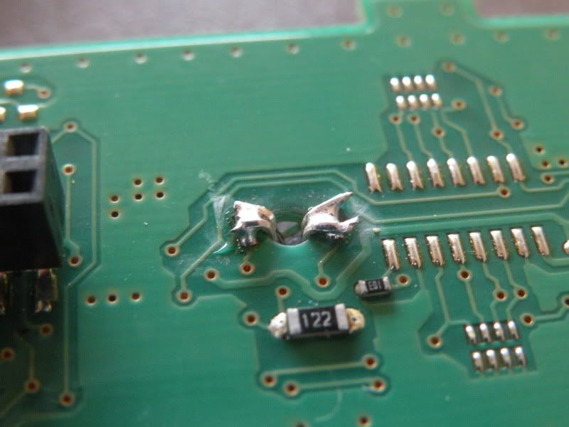
The factory switches have smd LED's soldered in place. Just touch the soldering iron to one side while using a small screwdriver to push against it to lift it up off the board, do the same for the other side and you'll have one of these guys:

20120407_171741.jpg


All you have to do is solder a blue LED in its place! No resistors! The board has already got resistors soldered into the tracer lines since the factory LED's are a warm white color....and white uses the same voltage drop as blue so its just swapping diodes!

For the passenger side you can just cut the legs off your LED to the same length. Build up a small mound of solder on the board where you removed the other LED's, then solder you new LED in place. (BTW in case you dont want to mess with the orientation of your LED's, the factory resistors should be your positive side!

Heres how i did the driver side:

Mikesdoorswitch002.jpg

Mikesdoorswitch001.jpg

Mikesdoorswitch003.jpg


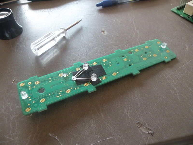
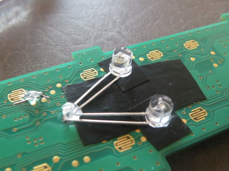
The driverside is a 2-piece. The main board on bottom, and the touch pad on top. For the driverside, the LED's actually mount underneath the top circuit board pointing up. So on this one, you'll need the LED leads long enough to curve under the existing holes, and solder from under the board. Replace the door LED, and the mirror select LED as normal, and for the window switches, you can do 1 per window switch since they're independent. Remember you're not re using the diffuser, so just take that out and toss it! And put a piece of electrical tape down where the leads of the LED are so they dont contact the board.

Heres how to orient the mirror select and door lock LED's for soldering:
20120407_173120.jpg


And thats basically it! You can get creative on how you do your window switch LED's but this is how i do mine.